We have moved to https://dokuwiki.librecad.org/
Lots of content was already moved to the new wiki, but there is still work to do. If you want to contribute, please register a new account at https://dokuwiki.librecad.org/
This wiki will be kept for a while to keep search engine results valid. Moved sites may be deleted here in future.
Layers
Contents
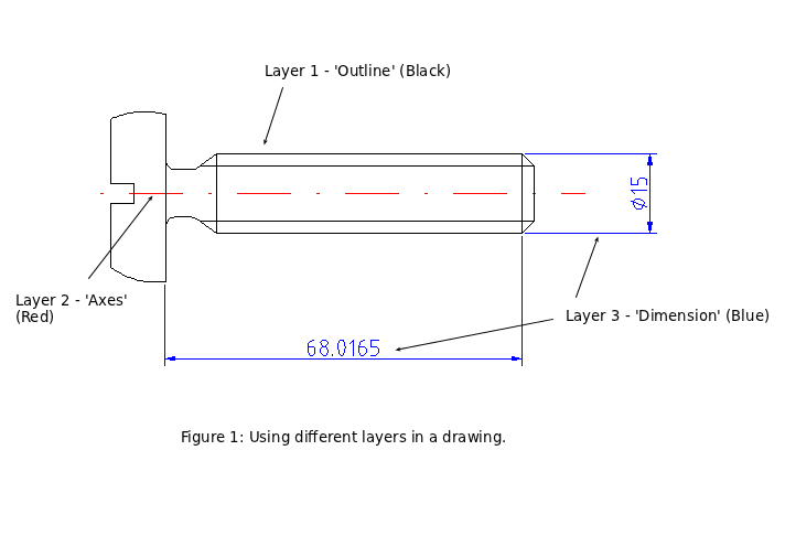
[hide]A basic concept in computer aided drafting is the use of layers to organize a drawing. Every entity in a drawing is on exactly one layer and a layer can contain lots of entities. Typically entities with a common 'function' or common attributes are put on the same layer. E.g. you might want to put all axes in a drawing on a layer named 'axes' (see Figure 1 below). Layers can have their own attributes also (colour, line width, line style etc.). Each entity can have its own attributes or have its attributes defined by the layer it is placed on. In the latter case for example you can change the colour of all the entities on the "axes" layer by setting the colour (red for example) for that layer.
In traditional manual drafting, a similar approach was used. Whether for Engineering, Architectural or Construction drawing etc. layers were used to show different aspects of a drawing — for example this could be a layer set up for showing centre lines on an engineering drawing or to show different building systems, such as wiring and air conditioning. The layers were often drawn on separate transparent sheets of paper. These sheets were then overlaid one on top of another to produce final drawings.
Creating a Layer
Layers are usually created to hold objects with common attributes. Creating a layer is easy.
- From the menu select Layer->Add Layer
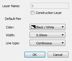
- Specify a Layer Name
- Optionally specify the Color, Width and Line Type
Changing an Object's Layer
Sometimes it is necessary to change an object's layer. This describes how to move one or more objects between layers.
- From the menu select Modify->Attributes
- Select the objects you want to change the layer of. See Selections for a detailed description of how to select objects
- Select the continue action button (double right arrow)
- In the Attributes dialog, drop down the Layer selection box and choose the desired layer.
Alternatively you can activate the option Application Preferences → Defaults → Modify layer of selected entities, at layer activation
With this option enabled you can move objects to a layer by selecting the objects and then selecting the destination layer.
Construction Layers
Note: Construction layers were previously known as help layers.
A construction layer is designed to hold geometry construction lines:
- A construction layer won't appear on printout;
- All lines of a construction layer are infinite in length.
You can toggle between construction and normal mode three ways:
- the right most layer icon

- right-click on a layer and choose "Toggle Construction Layer".
- the checkbox in the layer settings window
Ordering Layers
Layers are displayed in alphabetical order in the layer list, and this is does not relate to the order that entities appear in the z-axis of the drawing. Each entity can be raised or lowered with respect to others, and each layer can contain entities that are at different points on the z-axis.
Use the four Draw Order commands (under the Edit → Draw Order menu) to move entities up or down the z-axis.

