We have moved to https://dokuwiki.librecad.org/
Lots of content was already moved to the new wiki, but there is still work to do. If you want to contribute, please register a new account at https://dokuwiki.librecad.org/
This wiki will be kept for a while to keep search engine results valid. Moved sites may be deleted here in future.
Starting to draw

This page presents a simple sequence of creating a basic drawing, from a blank document to a printed design. It assumes that you have installed LibreCAD and have opened it to a new default blank drawing. It introduces quite a few LibreCAD concepts, and links to other pages that explain these.
You can download and unzip File:Carport.zip to compare your results with what the authors of this document saved.
Contents
Sketching
The first part of any design is a freehand sketch on paper. This is quick and simple and so allows for greatest freedom in the design process.
Example
We'd like to create a drawing of the following aluminium structure which sits on top of a carport.


Start a drawing
- Start LibreCAD -
- Check your version via the Help/About menu item - the example here have been created with version 2.1.3
- First you might want to decide about your application preferences using Options/Application Preferences/Appearance (in Version 2.0.9 Edit/Application Preferences)
- For this example the background color has been changed to "white"
- Save the default "unnamed document 1" as "CarportEast" using the "File/Save" Menu
- Check that the save was successful by Quitting LibreCAD, and restarting it. The saved file "CarportEast.dxf" should show up in the "File/Recent Files" Menu
- Reopen the file and close the "unnamed document 1" by clicking the circled x in the tab.
Scaling
We'd like to have an A4 drawing on which a scaled version of the 5000 x 1300 mm construction fits.
A4 is 297 x 210 mm so if we make the 5000 mm be shown as a 250 mm long line we'd be set. That is a 1:20 scale.
Via the menu Options/Current Drawing Preferences/Dimensions we can set the General Scale to 20 to achieve the scaling. And set Landscape for the paper direction.
Construction lines
The first lines of any technical drawing are the construction lines, setting out the locations of all lines without specifying any line types, colours, etc. All straight construction lines are of 'infinite' length — i.e. they extend off the screen in both directions.
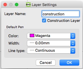
- Create a new Construction layer by clicking the "+" sign in the Layer list. The new layer might have a name such as 'construction', and a colour of magenta or cyan or similar. The line's width should be '0'.
- Make sure Snap on grid is enabled.

Drawing Box
We'd like to create a 5000 x 1300 mm construction line drawing box in which our construction will be placed. Since we want precise positions for this box we'll use the Command Line Mode and create a Polyline. Note: Command Widget must be displayed (Widgets, Dock Widgets, Command Line).
- Hit space to enter the command line mode - the cursor will jump to the command box (bottom or lower right corner) and "Command" will be in blue (you can type clear in the command box if the state of things is not like that)
- Type polyline or "pl" - you'll now be asked for the points
- Specify first point: 0,0
- Specify next point: 5000,0
- Specify next point or [undo]: 5000,1300
- Specify next point or [close/undo]: 0,1300
- Specify next point or [close/undo]: close
Zoom out with the View/AutoZoom menu item You should now see a 5 x 1.3 m rectangle at 1:20 scale

Try printing the page with File/Print - the printout should be empty since the construction layer will not be printed
Drawing the frame
For the frame we would like to create three "rectangles" that represent the sides of the frame. Each side has 40 mm width, so we simply take the three corners of the triangle:
- 0,0
- 5000,0
- 5000,1300
and shift the coordinates by 40 mm accordingly.
Select the default layer in the Layer list by clicking on it

Add three more polylines in the default layer:
pl
0,0
5000,0
5000,40
0,40
close
4960,0
4960,1300
5000,1300
5000,0
close
5000,1300
5000,1260
0,0
0,40
close
Should you have made a typing error you might want to use the "undo" command to remove the latest drawing item that didn't go as you intended. Hint: You should type these commands to learn the process but in future you can copy/paste multiple commands using the special command action on right of command line.
You might want to save your result with File/Save. This time if you print things out with File/Print the result should be visible. You can also check what the print looks like with File/Print Preview which will open up a new tab

You'll find a saved version up to this step in the file File:CarportEastStep1.dxf or in the zip file mentioned above.
Adding the freehand sketch (optional)
To support the transition from the freehand sketch to the LibreCAD CAD drawing you can optionally insert a scanned version of your freehand drawing as an image.
- Click the "Insert Image" button
- Select the file of the freehand drawing File:CarportFreehand.jpg
- position it where you like (e.g. on top of the drawing box)
- Note: in draft mode an outline is displayed instead of the image - view in print preview or turn off draft mode

Drawing the support beams
The next three polygons are a bit more tricky. We need to find out the positions to use from the dimensions we measured. Fortunately for the math there are helpers on the internet:
- Via https://www.calculator.net/slope-calculator.html (using "If the 2 points are known")
we find out
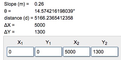
For a triangle to be calculated we need three values.
For the three beams we only have the length and slope 14.57 degrees at this time:
- 363 mm
- 845 mm
- 1050 mm
But we can also see that we have two angles available:
- 14.57 degrees derived from the frame triangle
- approx 90 degrees at which the beams are attached on the top side
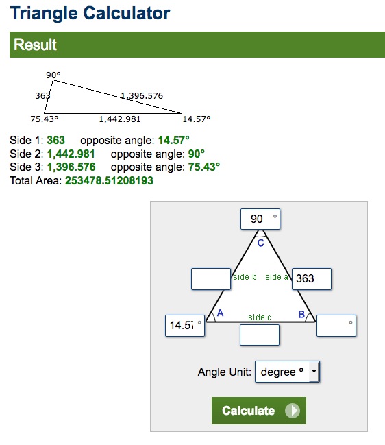
Since we have three values of the triangle we can calculate the other values with
Construction Triangles for Beams
We'll add the triangles in the construction layer using LibreCAD's capability to use relative and polar coordinates
- Select the construction layer in the layer list
- press space to enter the command mode (type clear if you want to get rid of old commands shown)
- enter the polygon for the triangle:
pl
0,0
1443,0
@363<104.57
close
The values are from the triangle calculator.
- 0,0 is the start point
- 1443 is the x position at which the 363 mm long beam leave the x axis
- it leaves at an angle of 75.43 which we have to enter anti-clock wise with makes it 104.57 (90 degrees more than the frames 14.57 angle) the new point is to be calculated relatively so we have used the @ symbol to denote this, the < symbol denotes that we are specifying a polar coordinate.
We repeat this for our other beams
0,0
3359,0
@845<104.57
close
0,0
4174,0
@1050<104.57
close
and end up with:

You'll find a saved version up to this step in the file CarportEastStep2.dxf in the zip file mentioned above.
Drawing the beams
For the beams we could now also calculate the points for the corresponding polygons. We do not need that much precision here so an alternative is to draw the beams with the mouse using our construction triangles as guiding lines.
Drawing the beams using the mouse
- select the default layer again
- select the polyline tool
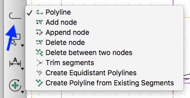
- for each of the three beam polylines you need to
- click four times at the positions to get three sides of the beam outline
- click "Close" in the tool option bar to complete the beam polyline back to the origin.

see https://github.com/LibreCAD/LibreCAD/issues/1036 for the question how the close button could be improved
Drawing the beams using the command line
We can make the point calculation easier by using relative coordinates. We know
- the lengths of the beams
- 363 mm
- 845 mm
- 1050 mmm
- the x cooordinates
- 1443 mm
- 3359 mm
- 4174 mm
- the angle 104.57 degreess
- the width of the beams: 30 mm
1443,0
@30,0
@363<104.57
@-30,0
close
3359,0
@30,0
@845<104.57
@-30,0
close
4174,0
@30,0
@1050<104.57
@-30,0
close
Beams result
The basic construction elements are now in place.

You'll find a saved version up to this step in the file CarportEastStep3.dxf in the zip file mentioned above.
Drawing Dimensions
We'll draw the Dimensions with precise values using the command box
da
0,0
5000,0
0,-100

Hint: If the dimensions are not shown clearly then check Options > Current drawing preferences > Dimensions.
We keep adding dimensions:
da
5000,0
5000,1300
5100,0

You'll find a saved version up to this step in the file CarportEastStep4.dxf in the zip file mentioned above.