We have moved to https://dokuwiki.librecad.org/
Lots of content was already moved to the new wiki, but there is still work to do. If you want to contribute, please register a new account at https://dokuwiki.librecad.org/
This wiki will be kept for a while to keep search engine results valid. Moved sites may be deleted here in future.
LibreCAD users Manual
User Manual for LibreCAD 2.2 << Click
User Manual for LibreCAD 2.0
Contents
- 1 Revision list
- 2 Preface
- 3 Introduction to LibreCAD
- 4 Overview
- 5 Changing program and drawing setting
- 6 Coordinates
- 7 Drawing lines
- 8 Dimensioning and text
- 9 Layers
- 10 Using Command Line
- 11 Pan and zoom
- 12 DRAFT VIEW
- 13 Info icons
- 14 Isometric Grid
- 15 Self Test
- 16 Further tools
- 17 Data import and export
- 18 Splines
- 19 Self Test 2
- 20 Collection of DXF examples
- 21 Technical background
- 22 Other resources
Revision list
Author of first version: Bob Woltz (2012 (?))
License: Creative Commons Attribution Share Alike (CC BY-SA 3.0)
Revision list:
- Bob Woltz: 2012
- Clive: 25 Feb. 2013 (transferred Manual to this web page)
- Dli: 15 Jul. 2013 (editing )
- Clive: 2 Aug. 2013 (editing)
- Ferdi: 28 May 2014 (editing and adding missing diagrams)
- Ferdi: 29 May 2014 (adding new paragraphs, first step to a living document)
- Ferdi: 30 May 2014 (continuous update, moved to this new address)
- Claudio Guarnieri: 3 June 2014 (spline tutorial part 1)
- Ferdi: 5 June 2014 (spline tutorial part 2 and others)
Preface
Bob Woltz wrote in 2012:
This is a user manual/guide for LibreCAD. I have written this manual using the KISS principle (Keep It Simple Stupid) this manual is designed in Chapters and simple instructions so that even someone entirely new to LibreCAD and CAD in general can learn to use it. This manual is designed for the user to follow along as the user is using the program in front of him. So it would be to the user's advantage to print out a copy of the manual to use to follow the lessons given. I hope you enjoy your learning experience. This manual is in English but permission is given to freely translate this manual into other languages and file formats.
Freelance wiki workers wrote in 2014:
Please don't hesitate to contribute your improvements as well.
Introduction to LibreCAD
With the release of 2.1.0 the old toolbar was replaced
with various alternatives, including the ability to create custom toolbars and custom menus.
Please read the new User Interface page for more information.
Overview
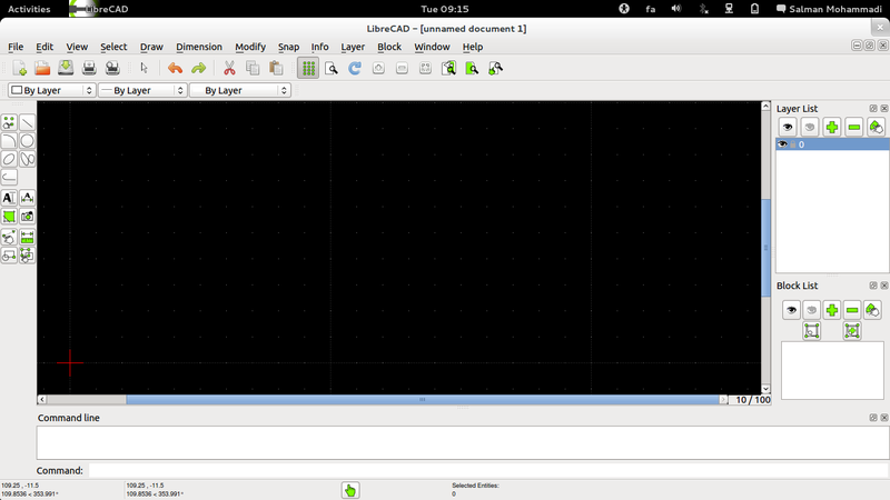
Go ahead and start up LibreCAD and take a look at what you see on the screen. Notice across the top there are words that you click on for pull down menus. Go ahead now and click on each word to see the menus. Don’t select anything from the menus as of yet, we will examine some of the selections in as we work through the manual.
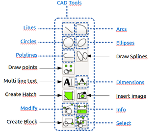
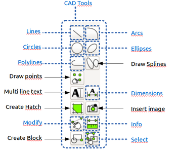
Notice Icons below the words. Put your cursor over each Icon without clicking and the program will show you what the Icon does. You will also notice Icons on the left side. Move your cursor over these Icons also and you will note information on these as well. The top 7 are drawing Icons, The next 2 draw text and dimensions, The next Icon on the left draws cross hatch and the one next to it is snapshot which is non-functional in this version, The last 4 open different menus and functions.
Notice at the bottom of the screen you will see the command line. You can actually draw in LibreCAD using commands that you type into this area. We will use this in a later lesson - to get you familiar with using the command line. Sometimes LibreCAD waits for special input: you should select an object or set a point. Look in this area, most of the time LibreCAD writes down here what it wants.
On the 'right-hand' side of the LibreCAD window you will notice areas for creating Layers and Blocks. We will use these in later lessons too!
The last (main) area we want to look at now is the Drawing area or the Workbench as it is sometimes called. This is where you will do all of your drawing, dimensioning, etc. You can also change the settings of the program and drawings too. We will examine this next.
Changing program and drawing setting
Let's take a look at the Program settings first.
First, click on Edit (Options since 2.1.0) at the top of the page from the main menu. Then select Application Preferences. Notice the box that pops up and also notice that you can change quite a bit here under appearances. At this stage we are going to use the 'defaults' the program has set up for us. Make sure however that 'Graphics View > Show large crosshairs' is selected, this option turns the big Red Crosshairs in the work area on and off.
Also make sure that 'Automatically scale grid' is selected.
Now click the tab Paths. Notice we can define folder destinations for things like fonts, hatches, part library items, templates etc. We want to create a folder for our Part Library and also our Templates.
The default directories are:
- Under Linux:
/usr/share/librecad - Under Windows:
C:\Program Files\LibreCAD\resources\library
You may change them if needed.
Next click on the 'default' tab, for now we will not change anything here, but notice that we can change the unit type — for instance we can choose Millimetres, Inch or Meter among others here!
Also, it is always good to have 'Auto backup' selected.
Now click ok to close the box and we will look at Current drawing preferences. Everything you do here affects the drawing you are currently working on ONLY. So let's take a look.
- Click edit, then select current drawing preferences. Notice the pop up box.
- Click on the Paper tab. Here you can change paper size and also paper orientation.
- Click Landscape and pull down the size menu and scroll to select letter. This setting will allow printing from a home computer. Also most drawing projects use a landscape orientation so that’s why we pick landscape.
- Now click on the units tab. Here you can change units like we did earlier but the choices are only in effect for this drawing. Here we may want to change the Length from 4 decimal places to just 2. Do this by clicking precision and selecting 0.00 from the pull down menu.
- Now click on the Grid tab. Here we want to make sure that show grid is selected and also orthogonal is selected. Notice you can select isometric grid too but don’t do that now, we will play a little bit with that later on.
- Now click the Dimensions tab. Notice there is quite a bit you can change, but we will leave that as is for now.
- Now click on the Splines tab. Here you can change line segments but again leave the setting as is. Now click ok to close the box.
We have now covered settings changes and we also now have a blank drawing that we can save that will automatically load these settings when we want to do a drawing.
- Now click file at the top, select save as, type blank drawing, and click save.
Congratulations, you just saved your first drawing.
Coordinates
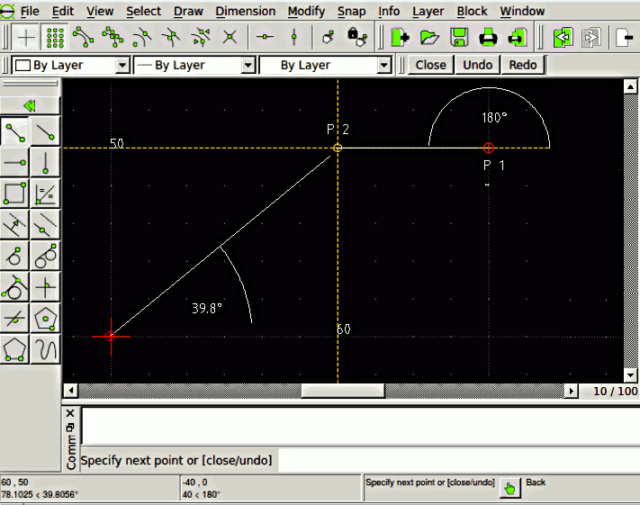
The red cross in the lower left drawing windows marks the origin of the coordinate system. Points and movements of the mouse are shown in Cartesian and polar coordinates in the lower left coordinate window. Additionally coordinates are given relative to a moving origin on the right to the absolute coordinates.
In the diagram I marked point P_1 first, then drew a line to P_2. The coordinate window gives its absolute coordinates: X=60, y=50 in Cartesian coordinates and a distance of 78 and angle of 38° in polar coordinates. P_1 is the reference point for the relative coordinates, visible as a small red cross. The distance between P_1 and P_2 is 40, the angle 180°.
There is one caveat: in the moment when second point P_2 was defined the line is drawn. But the relative origin remains on P_1. It jumps to P_2 when you move the mouse away from P_2, a mouse click is not required in this case.
You observe the same behavior after choosing Draw / Points. You define a new reference point by mouse click. It is the new relative center after mouse is moved after the click.
The drawing window looks like a fractal structure. It does not matter how much you zoom in or out, the lines keep their size. But there are other elements with possess absolute size: Text, arrows and hatching. You should have a close look to the numbers in the bottom right corner of the program window. They should be 10 / 100. The smaller number tells you the distance between grid dots, the larger between grid lines. If we chose 1 mm as basic unit (see dimensions below), then the basic grid has 10 mm distance, the lines 10 cm. Two lines cover an A4 page.
Drawing lines
Now we are going to begin drawing in LibreCAD. We will start with lines. Lines can be anything from lines to circles, rectangles, Arcs, ellipses, splines, polylines, and even text. We can even change the color, thickness and properties of the lines. You will learn how to do that in this lesson.
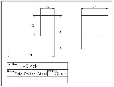
Above you see an example of a simple part drawing that a tradesman might get from an engineer to make. It contains all the information needed to make this part.
So now let's look at drawing lines.
Ok, let's begin,
- Click file at the top of the page, then open and click on the file we saved earlier called blankdrawing.dxf
- Before we go any further, look at the big red crosshairs at the bottom. It is important to note that the horizontal line in the crosshair denotes the X coordinates direction and the vertical line denotes the Y coordinates direction. The center point of the crosshairs denotes X=0, Y=0. Usually all drawings start at 0,0 so for the most part, the first point of your first line will start there. The points of the grid are spaced 10 millimeters apart so, that means if your crosshair center is 0 then moving right of that on the X (horizontal) the next point is 10 millimeters (from the crosshairs) the next point is 20 millimeters, the next 30 millimeters and so on. Moving from the crosshair center (0) upwards on the Y (vertical) the next point is 10 millimeters, then the next point is 20 millimeters and so on. This will be especially important when we draw some lines from the command line on the bottom. If all this is hard to remember don’t worry, we will create a help layer later on as a reference.
- Before we draw anything, click file, then save as, then type lines and save the drawing. What we did was put the blankdrawing file away and now we have a file on your workbench called lines. This is the drawing we will use for practice ===drawing lines===
- Select snap from the top menu then select snap on grid. This will make it much easier to draw straight lines.
- Select draw then move your cursor down to lines and then over to 2 points and select it. We are going to draw a line using 2 points.
- Move your cursor over to the red crosshairs. Notice that your cursor is now a crosshair and you have orange reference lines following it as you move to the red crosshairs. Notice also that the red point snaps from point to point on the grid now.
- Put the crosshairs on your cursor over the center of the red crosshairs and left click 1 time.
- Without clicking move your cursor 50 millimeters to the right (along the X axis). Remember that each point represents 10 millimeters. When you get there, put the crosshairs over the point and left click once, then right click 2 times to come out of the drawing command. You have created a line.
- Save your work thus far by clicking file save or the disk Icon at the top under the menu bar.
- We can also draw several lines one after the other easily.
- Click draw, then lines and choose 2 points. You will notice that there is a red point where you left off drawing the last line.
- Move down and left click on that point 1 time.
- Without clicking the mouse move your crosshairs (cursor) up (Y axis) 50 millimeters and left click 1 time.
- Now without clicking move your crosshairs (cursor) to the left 50 millimeters. Left click 1 time only.
- Now move your crosshairs (cursor) down 50 millimeters to the big red crosshairs and left click 1 time, then right click 2 times. You will notice that you drew a square. This is the way that you can draw several lines in sequence at one time.
Rectangles
Of course if you need to draw squares and rectangles there is an easier way to do it.
- Click on draw, then line, then select rectangle.
- Move your crosshairs (cursor) down to any point to the right of the square you drew and left click 1 time.
- Without clicking move your crosshairs (cursor) diagonally down to any other point and left click 1 time, then right click 2 times and notice that you have drawn a square or rectangle easier and in less time. Now you have another drawing tool in your arsenal of tools.
Circles
We will now draw a circle.
- Click on draw, then circle this time then select center, point.
- Move your crosshairs (cursor) into the first square we drew. Select any one of the center points and left click 1 time.
- Move your crosshairs (cursor) to the right 10 millimeters (that is the next point over) and left click 1 time then right click 2 times. You now have drawn a 20 millimeter circle inside the square. This is just one of the many ways we can draw a circle but the center, point method is used most often.
- Save your work at this point by clicking file, save or the save Icon below the top menu.
Now, we are gonna do a little teaser using the modify option. We will work with modify at a later time but I wanted to tease you a little.
- Select modify, move down and select stretch.
- If you notice on the very bottom of the screen you will see a green hand and you will notice it says specify first corner ( this is a prompt to help you ). It will always show you what to do next. Quite handy, and it is a feature we used often when learning C3P when I taught it. Let's continue now.
- Select the top right point on the second rectangle or square that you drew.
- Move your cursor without clicking to the right to the next point and then move your cursor down to the bottom point that is 10 millimeters away from your square or rectangle. Click 1 time. Notice the prompt on the bottom is asking you to choose a reference point. Move your cursor over to the right edge of your rectangle and left click anywhere on that line.
- The prompt now asks you to select a target point. Move your cursor to the right 10 millimeters (1 point) and left click 1 time, right click 2 times. Notice you have made everything longer on that on side by 10 millimeters. You can also use this method to shorten the side too.
Just thought I’d throw that in as a teaser. But now it is time to save your work once again so do it now.
Toolbar
So far we have used the menu on top to draw with. Some people prefer to use icons to access tools on a toolbar. If you look on the left side you see 2 columns of icons on the toolbar. When you click the icons a new toolbar with different icons appears. Let's see how that works. Move your cursor over to the left and place it over the slanted line icon. You immediately see a different toolbar appear. These icons have to do with drawing lines. Remember when we drew a line using 2 points earlier? Well, if you click the icon that has a slanted line with a green point on each end, you will be able to draw the same kind of line we did from the menu earlier. Also, you can see an icon that has a rectangle and 2 green points and this will allow you to draw a rectangle like you did before. Try it now and see for yourself. You now have a choice…you can draw with the menu across the top or use the toolbar. Different people have different preferences.
Our workbench is pretty cluttered now so let's delete some lines. It is very easy to do this.
- Move your cursor over to the circle you drew and click on the edge 1 time. Notice the circle turns to a red dotted line. This means it has been selected.
- Now, simply push the delete key on your keyboard. You have deleted the circle. One thing to note is if you delete a line by mistake, you can always bring it back by clicking edit on the menu bar and clicking undo.
- If you want to delete everything you drew, than the easy way would be to select “select” on the menu bar and then click on select all. Then press the delete key on your computer. Everything is deleted but, once again, if you made a mistake then select edit and then undo to bring it back.
Moving a line
Sometimes it is necessary to move a line because we need it to be in a different place, and this can be done either by dragging or by the Move/Copy action. Let's see how that is done by dragging:
- Select a line to move. Simply move the cursor over to the line you want to move and click on the line 1 time to select it.
- Drag the line selected. now touch the line with the cursor and hold the left mouse button down.
- While holding the left button down, use the mouse to move the line, and a preview of a line moving together with the cursor is shown. Release the left mouse button, after the preview is visible.
- Use mouse to move the preview to a new location and left click the left mouse button one time to accept the new location. You can see the line has been moved.
- To deselect the line, click on the line with the left mouse button 1 time, use the shortcut Ctrl-K or Selection Pointer within toolbar.
As you can see, it is very easy to do. This also works with circles, ellipses, and all lines. The one thing you have to remember though is if you want to move a rectangle or square you need to select each side first. (If you select only one side then only one side will be moved).
Now is a good time to save your work so go ahead and do that.
Changing Line Properties
Ok, we have drawn our drawing and now we need to change some of the line properties. We can do this through the modify menu. We can change line colors, line thickness, type of line, and even change length and location through this menu. Let's see how that works.
- Make sure you have at least 1 line drawn on your workbench. If you don’t, then go ahead and draw one.
- Once you have this, go ahead and click on modify on the menu bar. On the pull down menu, select properties.
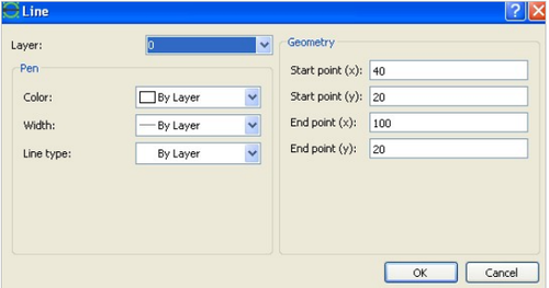
- go ahead and place the crosshair on a line on the workbench and left click 1 time. You will see a popup box like the one shown below.
Let's take a look at the line box. Look at the choices on the left color, width, and line type. For color, you can change the line color of the selected line by clicking the color menu and selecting he color you want. Go ahead now and select the color green and then click ok. Notice the line on the workbench is now green. You can change the line color as many times as you wish using this method.
Let's look at line type now. Put the white crosshairs over the line again and click. Our line box pops into view again and this time we want to click the line type and a pull down menu will appear. Notice you have many different line types to choose from. We will select dash from the pull down menu and then click ok. Notice the line on the workbench is now a dash line. In a drawing, a dash line usually denotes a hidden feature. If you remember the L-Block drawing earlier you see a dash line on the front view because base surface is hidden from view in the front view.
Line width is changed in the same way. You have choices on how thick the line should be and the selection works the same way as the other two.
Why don’t you take some time now and experiment with line modification. Try drawing some circles and rectangles too and see how line modification works for them as well. When you are finished, go ahead and put away your line drawing by saving it and then click close.
Dimensioning and text
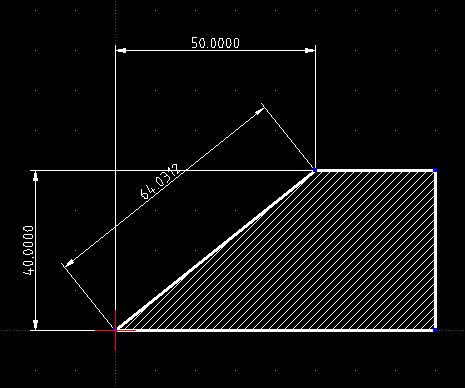
Dimension / Aligned = 64.03; Dimension / Horizontal (Dimension / Linear) = 50.0; Dimension / Vertical = 40.0
We have drawn our work and now we need to add dimensions and text. First of all, let's look at dimensioning a drawing. It would also at this point select edit then current drawing preferences and then dimension and make sure the text height is 2.5 and if it is not, then change it to 2.5 and click ok.
Dimensions
To start we need to create a drawing. So let's start a new one.
- Click file, then open, and select blankdrawing and bring it back out on the workbench.
- The first thing you are going to do is click file, then save as and type dimension and text and then click save. We now have a new drawing called dimensions and text on the work bench.
- The first thing we need to do is draw a simple object to dimension so now is a good test to see how much you remember from the drawing lesson. Pick and spot on the workbench and draw a rectangle. It can be any size or shape you want. Go ahead and do this now. If you have a problem, refer back to the drawing section of the manual.
- When you have finished go ahead and save your work by clicking file, save or the save Icon on the top.
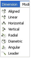
- Now click dimension from the menu bar on top. You will get the pull down menu as shown below.
Let's look at the menu a moment. Notice several options are available to us. The first 4 are for dimensioning lines, the next 2 allow us to dimension a circle by defining either the radial (radius) or diametric (diameter) of a circle. The next one, angular, will give us the angle in degrees of an object. The last one is leader which is used with text in a drawing and we will use that later in drawing. So now let's continue:
- Enable Free Snap along with Snap Endpoints.
- Select horizontal from the dimension menu.
- Move the crosshairs over either the left top point or bottom left point of your rectangle and click 1 time.
- Move the crosshairs horizontally to the right to the right edge of the rectangle and click 1 time
- Without clicking the mouse move the line up or down and you will notice the dimension appears. You can now place it where you want to and when you are satisfied left click 1 time to set it and then right click 1 time to come out of horizontal dimensioning.
- Notice the Icon menu on the left side now. You can select a dimension option from that menu also now. (as long as you only right click 1 time when you finish a dimension the dimension Icon menu will be on the left).
- Select vertical from the Icon menu and select the upper left point of the rectangle and click 1 time.
- Move down and select the bottom left point of the rectangle and click 1 time.
- Without clicking move your mouse to the right and the vertical dimension appears. Move it where your want it and left click 1 time and right click 1 time and now you have dimensioned the rectangle. If you don’t like where you put the dimension, or you need to make room, you can move the dimension as follows:
- Put your cursor on the dimension line and click 1 time.
- Notice the line turns to a red dotted line to show it's selected. Notice also a blue point by one of the dimension arrows.
- Touch your cursor to the blue point and hold down your left mouse button. Keeping the button held down move your mouse and you will see the dimension move with the cursor. Move the dimension where you want it and left click 1 time to set the new position. If you are satisfied then right click 2 times to come out of the command otherwise grab the blue point again and move it where you want it. Then left click 1 time and right click 2 times.
- Click on the line 1 time to deselect it. You will notice the line change from red back to white.
Now let's draw a circle. Put the circle in any available open space. Again, if you have problems, refer back to drawing a circle we covered earlier. This is good practice for you too. As we go further into the manual, you will become more familiar with drawing that it will become like second nature to you.
To Dimension the Circle:
- Select Dimension and click Radial on the pull down menu.
- Touch the edge of the circle with your cursor and click 1 time.
- Without clicking your mouse, move it away from the circle. Notice the dimension appears. Now move the around the circle and you will see the dimension moves around the circle. Pick a spot you want your dimension and left click 1 time and right click 1 time to come out of the command.
- If you are not happy with where the dimension is, then you can move it again by clicking on the dimension and notice it turns red to show it's selected.
- Touch the cursor to the blue point on the edge of the circle and hold the left button down. Notice when you move the mouse you can move the dimension. When you have it where you want it release the left button and click the left button 1 time. If you are happy with the position right click 1 time to come out of the command and left click 1 time with your cursor on the dimension to deselect it and the dimension will change to its normal white color.
- Take the opportunity to save your work now.
Dimensioning the diameter of the circle is done the same way as the radius. I want you to do that now by yourselves. Again, this is good practice and kind of a self-test to check how you are doing. You can use the dimensioning a circle as kind of a guide if you get stuck (just remember that when it says radius, to substitute the word diameter). Go ahead and try it now. One other point I want to make here on dimensions. You can change the color of your dimension if needed. You do this by clicking modify on the on the menu bar on top and then clicking properties. Put the crosshairs over the dimension and click. A box will pop up and it has a pull down menu under color that will do that for you. Just click on a color and then ok and you will see the new color on your dimension. To change a dimension height, then click on edit on the menu bar and choose drawing preferences. Click the dimension tab and change the height area by typing in a new value. Then you click ok and the dimension size will change.
Drawing a leader line
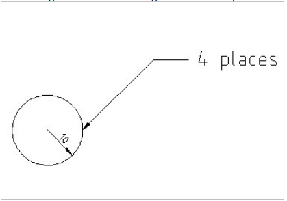
Notice that I said draw. This is not on the drawing menu itself, but is found on the dimension menu. A leader is usually used together text as part of dimensioning a drawing. It is adding a note to the drawing. Note the example below.
This is a way of adding a note to a drawing as a way of communicating information about the particular entity. A tradesman would look at this note and know that there are 4 holes and they are all 10 mm. radius even if the other 3 holes were not dimensioned. Since we are using dimensioning and text this time it will provide a good lead in to our discussion of text in this chapter.
Let's try drawing a leader. Use the circle you created in the last exercise:
- Click dimension from the menu bar at the top. The leader is the last option on the pull down menu so click it.
- Move the cursor down to the circle and click on the top right edge of the circle.
- Without clicking move your cursor diagonally away from the circle about 20 mm and left click 1 time.
- Move your cursor horizontally to the right about 10mm then left click 1 time. This sets the position. Right click one time to come out of the command. Notice an arrow is now on the leader on the end that touches the edge of the circle.
- Now save your drawing by clicking file save or the save Icon above.
This completes the drawing of the leader. All that is left now is to add text.
Adding Text to a Drawing
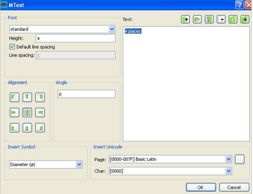
Now we will add text to the drawing. This adds notes and other important information to our drawing. Notice on the left Icon Menu there is a large A Icon. This is the text Icon. Click on this Icon now and a text box will open like the one below.
Let's take a look at this box:
Notice there are many options you have. Starting on the top left you can choose the Font. Click the arrow and you can see on the pull down menu you have several fonts. We will play with these options a little later but for now, choose the standard font.
The next option is text height which is how big the text will be. We don’t want it too big or too small so 4 would be a good height to type in that box. So go ahead and do that.
Next down is spacing and the default spacing is good so leave that as is.
Move over to the right side now and click inside the text box. You are going to type 4 places and then click ok on the bottom. The box will close and you notice you have the yellow reference lines and the words 4 Places by the crosshairs. Use your mouse to move the text up by the right end of the leader and left click 1 time and right click 1 time to set the text. You can move the text by clicking the text to select it ( at this point you might want to turn off grid snap by clicking the snap on grid Icon on the lower top Icon menu). You will notice when you clicked on the text, it turned red to show it is selected and there is a blue point by the text. Put your cursor on this blue point and hold down the left mouse button and move the text where you want it and click the left button 1 time and right click 1 time. Your text is now where you want it.
Save your work again at this time.
Now let's look at the text box again.
Look at the font area and click font and look at the choices. Usually for drawings you will use either the standard font or the iso font but there are many more choices. Notice below that the height option also. Within the height box you can type in any size you want. The lower the number the smaller the text and the larger the number the larger the text. I am going to leave it to you now to type a word or two into the text box, select a font, type in a height click ok and insert the text into the drawing where ever you have some space. Try it several times with different fonts and sizes for practice. Get a good feel for this so you will become very familiar with it. When you are done, save your file and close it to put it away.
Layers
Now we are going to touch on Layers. These are especially important in certain drawings. I want to point out one example now and I am going to get kind of technical here so please bear with me. Engineers will understand what I am saying but this may be more challenging to understand for others so I am going to try to make it as simple as I can. Layers are especially important in Assembly drawings. An Assembly drawing is a drawing showing 2 or more parts as an assembly on a drawing. Each part is drawn on its own layer. When all the layers are shown on the drawing, you have the complete assembly in view. In the Automotive industry, an Assembly drawing may show a complete car with 50 or more layers each layer showing a different part. Not only do they show the parts, but also how they fit together in an assembly. By studying this you can find any mismatches that may occur in assembling the vehicle. Having been in the Automotive industry myself, I can’t tell you how many times I have looked at these drawings and found gaps between parts which wouldn’t allow the parts to be welded together or parts too long that would interfere with other parts. By seeing these mistakes before the car goes into production, it can be corrected quickly. If not found before production, then this causes car recalls that you see now and then or halts and delays in production of the car.
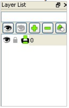
So now we are going to work with Layers. But before we do so, let's take a look at the Layer box area. This is located on the right side of the work bench. The Illustration below shows the Layer box.
Looking at the Layer box we note some Icons. The eyeball turns on and off the Layer’s visibility. The plus sign when we click it will produce a new Layer and we will look at that in a minute. The minus sign will delete a layer and here you must be careful because it is very possible to accidentally delete the wrong layer so be careful. The last Icon on the right is the modify Icon and allows us to modify the attributes of the Layer or rename it.
Below the Icons we have the Layer list. Here all the Layers in the drawing will be shown and if they are visible or invisible and if they will print.
We will create a Help Layer now.
Construction Layers
Note: Construction layers were previously known as help layers.
A construction layer is designed to hold geometry construction lines:
- A construction layer won't appear on printout;
- All lines of a construction layer are infinite in length.
You can toggle between construction and normal mode three ways:
- the right most layer icon

- right-click on a layer and choose "Toggle Construction Layer".
- the checkbox in the layer settings window
First of all, click file and then open and bring your blankdrawing.dxf out onto the workbench then go ahead and click on the plus Icon in the layer box now.
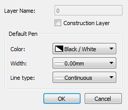
Notice a Layer settings box pops up like the one above. Click in the layer name box and delete noname and type reference. Next check the box construction layer. In the default pen area, click color and then choose red. What this does is make the default drawing color red so that all lines and text drawn on this layer will be red. Leave the rest as is and click ok. Notice on your layer list you have a reference Layer now. Go ahead and save the drawing by clicking file and then save. What we have done is saved this layer as part of our blankdrawing.dxf so that when we use this blank drawing the reference layer will always be loaded with the drawing.
Now we are going to add some reference text to this layer.
- Click either draw, text or the text Icon on the left Icon panel.
- The text box will open. In the text box type X. Make sure it is a capital X. In the height box type 5 and then ok at the bottom.
- Drag the X down below the Big Red Crosshairs and move it to the left about 50mm.
- Left click 1 time and right click 2 times. The X is set in position.
- Repeat step 1. In the text box type Y. Click ok
- Drag the Y to the left of the Big Red Crosshairs and up 50mm from the Crosshairs.
- Left click 1 time and right click 2 times and the Y is set in position.
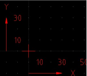
We are now going to use the leader drawing command to draw a couple of arrows. This will further help us to define direction. We want everything to look as in the picture below.
To get the arrows:
- Click dimension on the menu bar and then leader.
- In order to place the arrow properly, we need to left click 1 time at the 30mm and move back to 0 and left click 1 time to set and right click 1 time to make the arrow appear. Do this with both X and Y coordinates.
- You can now add numbers if you wish like I did using the text box like we did before. This will complete our reference layer for now.
- Click save or the save Icon to save the layer as is.
This reference layer will especially help us when we use the command line to draw lines. It will also remind us of the X and Y axis and which is which.
Using Command Line
There is another way of drawing in LibreCAD. By using the command line we can place entities specifically and accurately in a location in a drawing. We can draw lines, rectangles, circles and more. The command line appears on the bottom of your screen in LibreCAD:
Notice there is a box next to the word command. This is where we will type our information. To activate the box click inside the command box, or press <ctrl> M or <space>. The word Command turns into blue to show it's activated and awaiting your command.
Before we use this box however we need to do 2 things. First, check whether we are in the right layer. If not, choose right layer on layer window and activate it for drawing. Also make sure your layer is not a construction layer. Otherwise all the lines you draw will be infinite, which is a special property of construction layers. You can right click on a layer and then toggle this state. There is also an icon next to the layer's name (#).
The second thing we should do is click file and then save as from the pull down menu. We will save this drawing as L-Block. Click save and we will be good to go with our first drawing. We are going to draw the L-Block using the command line. The L-Block is an actual Automotive fixture part used in the fixtures that surround a car as it is being built. It is used as a stop block in the fixture to hold a part in correct position for welding.
To use the command line we need to know some things first. You notice in the drawing there is an X axis which is horizontal direction and a Y axis which is vertical direction. When you use the command line you are entering points on the drawing. The grid is a guide for you and the red crosshairs represent 0 on the drawing….that is 0,0 or X=0,Y=0 so when you enter points it will always be X,Y with the X always the first dimension. You will understand this better when we actually run through the exercise. So now let's give it a try: if you make a mistake click edit, undo from the menu bar.
- Left click one time in the command line box. The word command should turn blue to show it's active.
- We have to tell it what we are drawing so type line and press the enter key on the keypad.
- It should be asking us now to enter the first point so type 0,0 and enter on the keyboard.
- Now it is asking us to enter the second point so type 70,0 and enter on the keyboard. You should see a horizontal line appear 70mm long. This is the base of the L-Block.
- We need to enter the next point so type 70,50 and enter on the keyboard. You will notice it drew a vertical line to a point at X=70 and Y=50. That is a 50mm line.
- Now type 50,50 and press enter. We have another horizontal line this time 20mm long.
- Now type 50,20 and press enter. This draws another vertical line for us 30mm
- Now type 0,20 and press enter.
- Now type 0,0 (or @0,-20, see below) to bring us back to our start point to complete our drawing of the L-Block . You can also type close to do this as well.
- Right click 2 times to come out of the command.
The coordinates refer to the absolute origin. In case you prefer relative coordinates put the character @ in front of the coordinate, e.g. instead of 0, 0 try @0, -20 for the last data point example.
As you can see, we can be very accurate drawing this way. If you wanted to draw a circle you simply would type circle and follow the command prompts. You can do the same with rectangle. Go ahead and experiment with those now. You might try drawing a 5.5 radius hole with the center point at the 100,70 for instance. That is an 11mm hole which would be hard to draw any other way. Take the opportunity now to save your drawing using file, save or clicking the save Icon.
Follow the link for A short manual for use from the command line.
Pan and zoom
Pan and zoom are very useful tools in LibreCAD. The zoom tool is invaluable when you need to move up close to an entity to work on it. This is especially true when the area is very small, or several lines drawn close together. As you will see in a moment, there are several ways to use zoom. Pan allows you to move the drawing up, down, right, or left. This is especially useful if your drawing is large. Pan and zoom are accomplished using the Icons below.
Starting from the left, is the zoom in icon. Click on this and you gradually zoom in on the drawing. The next Icon is the zoom out icon. Click on this and you gradually out on the drawing. The next Icon is autozoom which zooms you in faster. The next Icon is the previous view Icon which when clicked returns you to the last view. The next Icon is window zoom which allows you to put a window around a certain area and zooms you right into the area. It is the fastest way to zoom in. I particularly love using this because I can get close up in a small area very fast, do my work, and click the previous view icon to bring me back out of zoom quickly. The last Icon on the right is Pan. Click this icon and place your cursor in the work area and hold down the left mouse button. You can move the drawing all over the work area and view the drawing area outside the work area also. You should still have your L-Block drawing out on your work bench so take some time now and experiment with Pan and Zoom. To use the zoom window:
- Click the zoom window icon
- Move your cursor down into the work area. Notice you have the orange reference lines and the cursor turns to a magnifying glass. Move the cursor by the area you want to zoom and hold down the left mouse button DO NOT RELEASE THE BUTTON YET but move the mouse to create a window around the area you want to zoom. When you have done that release the left mouse button and you will zoom right into the area. The smaller the zoom window you create, the closer you will zoom into the area.
- When you are done, click the previous view icon to zoom back out.
Pan and Zoom by mouse wheel
Zooming and panning can be achieved by mouse wheel scrolling. By default, wheel scrolling triggers zooming-in/out around the mouse pointer; holding down the Ctrl/Shift keys on keyboard while turning the mouse wheel triggers vertical and horizontal panning, respectively.
Zooming around the current cursor position is also triggered from keyboard by: Ctrl +/-. Holding down the Ctrl key allows, the view can be grabbed and dragged by mouse.
- zooming around the current cursor, Mouse wheel or keyboard shortcuts: Ctrl +, Ctrl -
- panning, Ctrl/Shift Mouse Wheel, or Ctrl and mouse dragging
DRAFT VIEW
There is also a "Draft" icon ![]() in the View toolbar. When pressing this icon, all your hatches become invisible, and all images and text only have their bounding boxes shown. You can use this, when you have a lot of hatches in your drawing and want prevent LibreCAD to slow down when rendering your drawing.
in the View toolbar. When pressing this icon, all your hatches become invisible, and all images and text only have their bounding boxes shown. You can use this, when you have a lot of hatches in your drawing and want prevent LibreCAD to slow down when rendering your drawing.
Info icons
On the Icon menu on the left you will find the Info Icon (green horizontal ruler icon).
With this icon you can actually measure an entity without having to dimension it. It is useful for checking your work as you draw or for a general check of information of an entity. When you click this Icon you will get the following Icon menu:
The top icon on the left allows you to measure point to point. The top right icon let's you measure point to a line.
The middle left icon let's you measure an angle. The middle right icon let's you measure total length of entities.
The bottom icon let's you measure the area of a polygon.
These icons are simple to use as you just click one point or entity and then click the other point or entity and the results will be displayed on the bottom in the command information box. Since you have the L-Block drawing on your workbench, go ahead and take a few measurements now.
Isometric Grid
Introduction
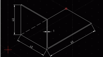
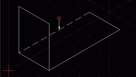
We use Isometrics when we want to show something in 3D. LibreCAD has an Isometric grid setting to enable us to do this. I know from experience that Automotive parts drawings usually contain a front view, side view, and top view in 2D and a small 3D isometric view of the part to assist in making the part. The craftsman making the part then has a good visual idea of what the complete part looks like. An Isometric view of a part might look like the diagram on the right.
This is a simple L-Bracket. Looking at this Isometric view you get a very good idea of how the part should look. What you see in this drawing is a metal L-Bracket with a 1 mm thickness. In a 3D CAD program you would also be able to shade the surfaces to make them solid surfaces and you would have 3D rotation to look at all angles at the part. Since this is a simple part, an Isometric view will suffice nicely for us. How do we make an Isometric view? We will look at this in steps as we draw our first Isometric view. In this drawing we will also learn some new drawing tools like drawing parallels, trim and extend, creating a radius on a part and even tools we already have learned like Pan and Zoom, Dimensioning, Changing line types and Basic drawing tools we have learned before. So, let’s get started:
- Save and close any drawings you have on your workbench.
- Click edit on the top menu bar. On the drop down menu select current drawing preferences.
- In the box that pops up select the grid tab on top. A grid options area will appear in the box. We are only going to change one thing here. Click the Isometric button and select ok on the bottom of the box. You will notice more grid points have appeared on the grid. That is because we now have a third coordinate we will draw on.
Take a look at this illustration:
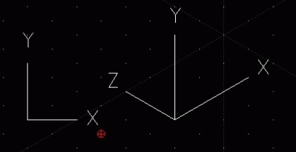
Up until now we have been drawing in the orthogonal grid which is the 2D grid. In the illustration above, the left side shows the X and Y coordinates, which show length and height. In the Isometric grid, we still have the X and Y coordinate, but now we have a Z coordinate which shows us depth or width now as well. I guess you could say that this is LibreCAD’s introduction to 3D drawing. It is limited, but then again, this is a 2D drawing program.
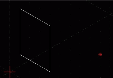
Turning back to the drawing on your workbench, click on file on the top menu and select save as. You are going to save the drawing as L-Bracket so type that and click save now. We will now do some drawing so click the line Icon on the left Icon menu and select line (the icon with the line and green points on each end) and move your cursor into the work area. The first thing you will notice is that the yellow reference lines now show the Y and Z coordinates. This is because we are drawing in Isometric mode. Everything we learned about drawing lines still applies here except for the Isometric angle. We are going to draw an Isometric rectangle to start our drawing. Normally we might use the rectangle drawing tool for this but there are certain drawing tools that won’t work when drawing on the Isometric grid and the Rectangle tool is one so we have to draw the rectangle with the line using 2 points drawing tool. When you finish the rectangle, it should look like:
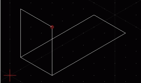
Your rectangle should look like the Illustration above. Don’t worry about size as this is an exercise to draw a basic Isometric drawing. The important part right now is the How and not the size. If you make a mistake, just click edit and undo to correct the mistake. Once you have a drawing that looks like the above, then draw the bottom of the L-Bracket. It should look like:
You now have the basic Isometric L-Bracket that looks like the Illustration above. As you can see, this does show a 3D object (showing Length, width, and Height). Now that we have the basic L-Bracket we need to make some minor changes and add thickness to the part. It is a good idea to save your work at this point, so do that now.
Line Modification
If you look at the L-Bracket you will see that part of the long line in the back runs behind or is hidden by the front upright part of the L-Bracket. In other words, if you looked at the part in real life you would not be able to see part of the back edge of the L-Bracket.
We need to change this line to a hidden line to show that part of the line is not seen. Normally, this is a simple change by making the whole line a hidden line but in this case, only part of the line is hidden. In this case it is a two step process to achieve this. The first step is to change the whole line to hidden and the next step is to use trim to remove part of the line and replace it with a solid line. Take a look back at the Illustration you saw at the beginning of this chapter and you will see what this will look like.
The first step is the line modification (properties):
- Click modify on the top menu bar.
- On the pull down menu click properties
- Move your cursor crosshair over the back edge of the part and click 1 time. The line will turn red to show it is selected and a line box will appear like the one shown below.
Click line type and all the available line types will be in the pull down menu. We will select Dash (small) from this menu and then click ok. Your part should look like the illustration below.
As you can see the back edge is now a hidden line.
Using Trim
To change the line we need to first trim the line and then redraw the part of the line trimmed as a solid line. This is done in two steps. First though, click modify again and the menu will again appear.
This time we want to select Trim from the modify menu. Move your cursor back into the work area.
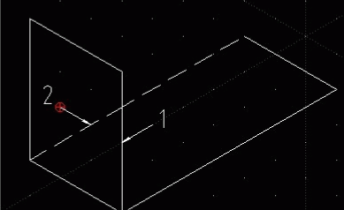
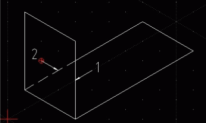
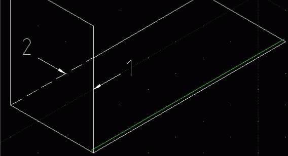
Center your cursor crosshair over line 1 and click 1 time. The line turns gray. In trim, the first line you select is the cutting line. Now move you cursor over and click on line 2 where shown. This is the part of the line you want to keep. The line to the left of the cutting line gets trimmed away. Now right click 2 times to come out of trim. Trim can also be used to trim away parts of the line that you don’t need any more like in intersections, etc. as well.
The only thing now left to do is click the Draw on the top menu and Line from the pull down menu and redraw the solid line from the point on the cut line (line 1) to the end point of the part. It should look like the Illustration below.
Remark: Redrawing is the second best solution. You can never be sure that your new line is exactly in line with previous one. In this case it is better to use Divide:
- Select Snap / Snap Intersection
- Select Modify / Divide
- Point to line to be divided and click left mouse button
- Point to intersection and click left mouse
- Click right mouse to exit Selection mode
- Click right mouse again to exit Divide mode
Nothing visible happened. But when you point the mouse to the line only one part will be selected after clicking left mouse. The line is divided and second part may receive different properties.
The basic L-Bracket is now finished. Take the opportunity now to save your work.
The next step is to add thickness to the part.
Creating Parallel lines
Because the L-Bracket is a metal part we need to add part thickness. We can draw this in LibreCAD by drawing Parallel lines. LibreCAD has a tool for that in the line drawing menu. Look at Draw / Line / Parallel or find right icons on left side icon menu in LibreCAD.
Once you have selected the top left icon for Line another menu will open and we will select the parallel line icon ![]() on the menu. After selecting the icon, We need to tell LibreCAD the distance we want between the lines.
on the menu. After selecting the icon, We need to tell LibreCAD the distance we want between the lines.
 We do this in the commandline. Move your cursor down to the commandline on the bottom and click left click 1 time.
If you look at the commandline it is asking you to specify distance. Since the L-Bracket thickness is 1mm you will type 1 on the commandline and press enter on the computer keyboard. You have now set the distance at 1mm and it will remain set at 1mm until you change it again. Move your cursor into the work area and note the parallel line will appear when you move close to a line on the part. Notice that if you move to one side of the line the parallel will be shown on that side. If you move on the other side of the line the parallel will be shown on that side. The line will not be drawn however until you left click the mouse button so please keep that in mind. We are now going to place the first line as shown below.
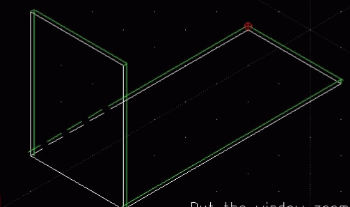
I have changed the color of the parallel to green for clarity in this exercise. Go ahead and place the line and left click 1 time. If you make a mistake, click edit and then undo to start over. You will now draw more parallel lines as shown in the illustration below.
Once you have finished drawing all of the parallels then right click the mouse 1 time to come out of the command. We are now finished adding the parallel lines we need. We do not add parallel lines to the back edges because of the angle on which the part is shown would place those lines almost on top of the existing part edges.
It is a good idea to save your work at this point so go ahead and do that now.
Connecting the corners
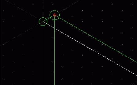
We now need to connect the corner points of our part. Because the lines are so close together we need to zoom in on the corners. I can’t tell you how many times I have seen people try to work with lines this close without zooming in closer. They spend several minutes trying to select lines and points only to become extremely frustrated. Please avoid this by using the zoom when working this close.
Remark: for quick paintings the recommendation above is good enough. If you are an experienced user please image points and lines as mathematical objects. They have only one dimension (line) or no extension at all (point). Theoretically it will be impossible to hit a point or a line by mouse pointer. When you connect lines there will always be a gap or an intersection. Solution: use Snap tools!
For zooming you may select the appropriate icons or open View / Zoom in. For heavy users it is recommended to use the mouse wheel:
- Mouse wheel will zoom in and out.
- Pressing the mouse wheel and move the mouse will shift the window.
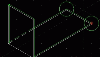
We are now going to draw a line between the 2 points circled. We do this by using the draw line Icon (or selecting draw) then drawing the line between the 2 points. You will need to use trim to remove any excess lines that run past the corners also. Go ahead and do that now. When you are finished use the pan icon (first icon on the right looking at the zoom icons above) and move to the other top corner.
Again instead of trimming using Snap / Snap on Endpoint may be the quicker solution.
Lengthening a line
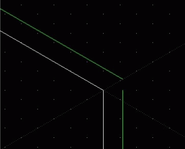
When you pan over to the other top corner you will notice a different situation:
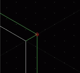
As you can see, the parallel lines don’t meet this time. That means we have to modify the line to lengthen it. We do this using the Modify menu: Modify / Lengthen
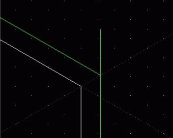
Once you do that move your cursor down to the commandline like we did for parallels. Click on the commandline and type 2 or 3 (this is how long we want the extension to be) and without clicking the mouse button move it on to the vertical line and click 1 time with the left mouse button.
The result is shown above in the illustration. Now all that remains in this step is to use the trim command to trim the excess line. If the other green parallel is short, repeat the process. Sometimes you may skip the step lengthen and trimming alone will give the desired result.
Now we need to draw the corner edge line. For this, we will use the draw and line between 2 point tool. There is one more thing we want to do now also. Move your cursor up to the Snap menu and make sure that Snap / free snap, Snap / snap on endpoints and Snap / snap on entity are selected.
Go ahead now and draw your line:
Now the corner is complete. So far we have done the top two corners. Using the tools we have learned, move now to the two back corners and complete them. Before you do, save your work at this time. Work on the two corners circled:
When you are finished save your work.
Creating a radius in a corner
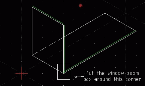
Every metal part needs a radius on the bend line. Our part has a 90 degree bend on one end. If we tried to bend this part without a radius, the part would break or crack on the bend line. For many years before I taught CAD, I worked in a metal shop. I not only worked on making parts like this, but also parts in different metal types in all different thicknesses and all different shapes (Automotive parts). If a craftsman looks at a part like this in a drawing, he or she would automatically put a radius in the bend even if it wasn’t shown because they know the nature of the metal. The metal needs to stretch rather than break or crack in the bend. So now let's work on the bottom front corners. Windowzoom in on the first corner as shown:
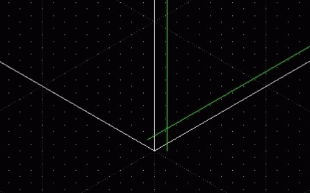
Now let's look at the zoomed in area:
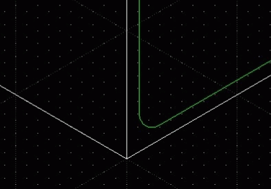
We will use line modify again for this task. Select Modify - Fillet’’.
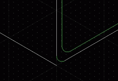
Move your cursor down to the inside vertical line and left click 1 time. Move your cursor to the other green line taking care that the radius shown connects the 2 lines and left click 1 time. The results are shown below.
Now left click on the vertical white outside line and then the bottom outside white line. Now you have finished the corner.
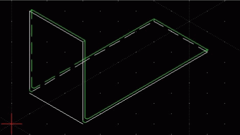
Go ahead now and pan to the other end and complete the part. Leave the white line left for a reference line. The completed part looks like shown below.
You will note some differences in what you have (hidden lines) and the finished part. Go ahead and make the changes in your part now.
Save your work now before something happens and you need to redraw it.
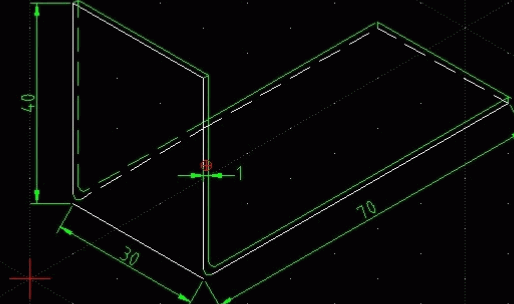
Dimensioning an Isometric Part
In dimensioning this part two things to remember.
- Vertical dimensions use the same method of dimensioning that we used before.
- For dimensions on the angle we need to use aligned dimensions.
Take a look at the dimension menu.
We are going to select Aligned and move the cursor into the work area. Start by dimensioning the lower front line. Everything works as it did before:
- Click on one end point
- Click on the opposite end point.
- Without clicking, move the mouse away from the line and left click one time.
- Move to the next line and repeat steps 1, 2, and 3.
- When you are finished dimensioning all the angular lines then right click 2 times to come out of the command.
Now click Vertical on the dimension pull down menu and dimension vertical lines. Your part should look like the illustration below.
Save your work now. This finishes the Chapter on Isometric Drawing.
Self Test
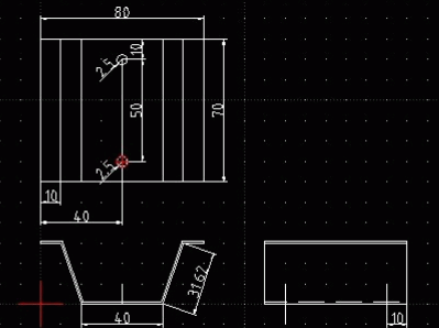
We have learned quite a bit so far. At this point I have included a self test. Actually, it is a drawing you can do to practice what you have learned so far (I guess this is the teacher part of me showing now) you don’t have to do the drawing, but I believe it will help to refresh and reinforce in your mind what has been covered so far. The choice though is up to you. Let’s look at the whole drawing for a minute.
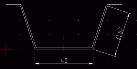
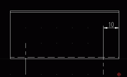
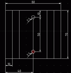
What you see is a small section of an Automotive part. It is a small section of the top inner side inner panel above the door opening in a car. Usually you never see the inner panel because it is covered by the roof on the outside and trim on the inside. It is very important though because the part is designed to protect you in the event of a rollover. What you are looking at is the front, top, and side views of the part. This is normally the way you would see them in a drawing and I, as a craftsman, would be asked to take a piece of sheet metal and make the part. But you do not have to make the part, just draw the drawing. I have drawn larger views below for clarity.
If you choose to work on it, save the drawing as hat section and later we will add a title Block to the drawing. Take your time and if you get stuck, go back in the manual to refresh your memory. If you want to draw each view as a separate drawing you can do that also. Also check the drawing because I purposely left out one thing to see if you can catch it (Just for fun).
Title Block
Every drawing usually has a title block. This provides a place on the drawing for extra information like part name, material, thickness, scale, and also a part or drawing number for filing purposes. You can make the title block as simple or complex as you want.
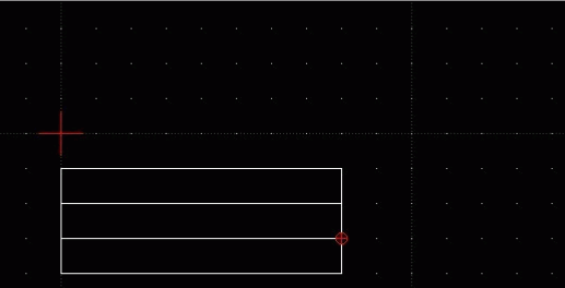
I drew this using the rectangle draw tool. I drew it 30mm x 80mm and then used the line drawing tool to divide it into 3 parts.
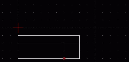
I also drew a vertical line as shown above.
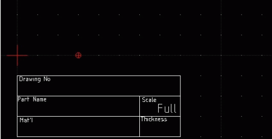
I then filled in the boxes as shown. I used the draw>text tool the label the box. I set the text height to 2 for the small text and for the large text I set the text height to 4.
I might suggest that you draw the title block on a separate layer on your blank drawing file that you saved earlier in the manual. This is what I did and now I don’t need to redraw the title block every time. If you create a layer call it title block so you will remember what is on the layer. You can make the block bigger to hold more information or change the labels in the boxes to suit your needs.
Projection View
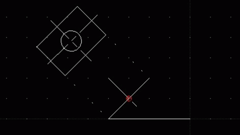
Before we leave drawing views I want to cover briefly one more type of view and that is a projection view. Sometimes our drawing has surfaces on angles. A front, top, or side view does not allow us to truly dimension it as it really looks and this is even truer if the surface has a feature like a hole, slot, etc. The only way we can show the surface in a true view (a view putting the angled surface 90 degrees to the work area). Below you will see an example of a projection view.
The top view is now a true view and allows us to dimension as the surface really looks. The view is drawn 90 degrees to the angled surface.
I know many of you are going to say that an Isometric view then is not a true view and you would be correct. Many drawings, at least the ones I have worked with, have front, side, top, and a small Isometric view somewhere on the drawing. The Isometric view is never dimensioned but drawn to show the craftsman what the part is supposed to look like. We dimensioned the Isometric view in the earlier drawing we did to demonstrate aligned dimensions.
Further tools
We are now going to cover a few more modify tools that will be useful to you. You may access them via the icon panel or via menu bar Modify.
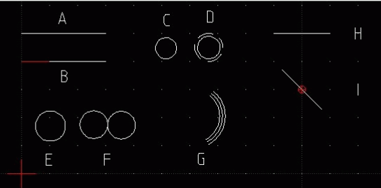
In example A, I drew a simple line. I then clicked in menu bar Modify / divide:
- One click on line I drew.
- The prompt on the bottom will ask me for a cut line or point. I then moved my cursor along the line and clicked at any point.
- I then right clicked 1 time to come out of the command.
Now if you go up and left click the line, you will notice you now have 2 lines. You have cut the line at the point you indicated. Example B shows the line I did and I colored one line red for clarity.
Please remember: lines are infinitesimally small. Sometimes it is difficult do touch a point on the line. If so, switch on an appropriate Snap tool.
In example C, I drew a circle via Draw / Circle / Center, point. By Draw / circle / Concentric I created another circle next to the original one I drew. This tool works the
same way the parallel line icon did. You simply select the tool and move to the
side of the circle you want the concentric on and left click 1 time then right click 1
time to come out of the command. The command line assumes 1 unit distance if not specified differently.
Example D shows the results (I used modify properties to change the line to a dashed line). By the way, on a drawing a circle drawn this way would indicate a threaded hole. In example G, I drew an arc and placed a line on each side using concentric.
In example E, I drew a small circle. I then chose the mirror tool, Modify / Mirror. I then:
- Clicked the circle.
- I then hit enter on the keyboard. The prompt on the bottom told me to select the first mirror point. I selected the right end of the circle. If you prefer you may press >> icon on the left in LibreCAD as well.
- The prompt then told me to pick the second mirror point so I moved the cursor away from the circle and down. A mirror image circle appeared.
- When I moved the circle where I wanted I left clicked 1 time to set it in place.
- A box popped up and I selected keep original and clicked ok.
Example F shows my results. You can also do this with a rectangle or any object you draw. Just make sure the whole object is selected before you press enter on the keyboard like it tells you in step 2.
In example H, I drew a line and then I selected Modify / Rotate. Then
- Select the line and then
- press enter on the keyboard.
- The prompt on the bottom will ask you to select a rotation point. I selected the center of the line.
- The prompt then asked me to choose a reference point so I clicked on one end of the line.
- The prompt now asks for a target point. Move your mouse and you will see the line actually rotate.
- Left click where you want to place it.
- A box will pop up and you will have a chance to change angle, keep or delete the original line, or create multiple copies.
I did that for fun and got what looked like an asterisk as a result but in this case I selected delete original and got the results in example I. Also notice in example you can see the rotation point I used is indicated by the red point.
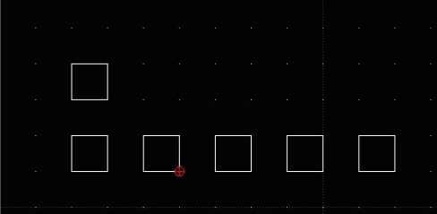
There is one more tool I want to go over and that is Modify / Move_Copy. I drew a small rectangle and selected the icon. Then:
- Select all 4 lines of the rectangle and
- press enter on the keyboard.
- Select a reference point. I selected the lower right point on the rectangle.
- Select a target point. I selected a point 20mm from the reference point.
- After you click a box will pop up. You can delete the original or keep the original, or make multiple copies. I selected multiple copies and typed 4 for how many I wanted.
- Click ok on the bottom of the box.
The result:
The top rectangle is the before and the bottom is the nice row I got from multiple
copies. I drew the top rectangle first then copy and moved it 1 time down to the
bottom and then used move and copy again to create the row.
These are some of the additional tools you will use most often in your drawing.
Hatching
Sometimes you would like to emphasis areas. You can do it by hatching.
Prerequisite: the object must be closed (see below).
Then:
- choose Draw / Hatch
- select the (closed) object(s)
- press enter
- choose a hatch pattern and press OK.
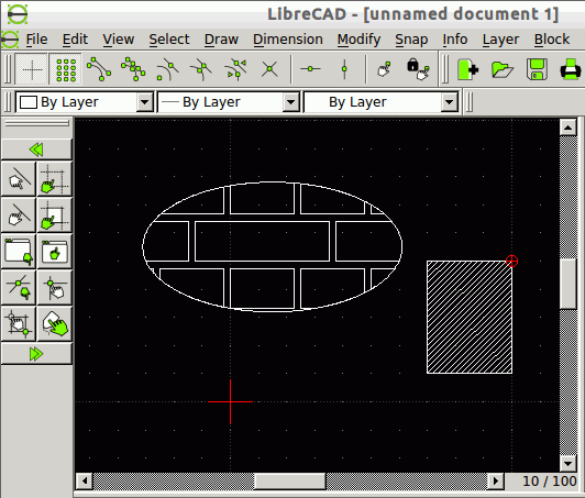
The examples were willed by pattern ansi31 and ar-brelm.
There is only one solid fill color (but many different colors for lines). You may use additional layers if you are short in fill colors. The hatching pattern are defined by files in dxf-format which you find in the hatch pattern directory, see Edit / Application Preferences / Path or its default values like /usr/share/LibreCAD for Linux.
How to change hatching pattern:
- Modify / properties
- hit hatching pattern by mouse
- select hatching of your choice
Possible errors
- Error message in command window
- It says: Invalid hatch area: Please check that the entities chosen form one or more closed contours
- Solution: Lines does not stick together. See closing below.
- Nothing happens
- If your fill pattern is too broad then your object may miss any of the fill pattern lines. For example, in the diagram above in the left hatching the vertical lines occur only every 5 units. If your object is smaller, no painting is visible. Try to choose the fill color instead of a pattern.
Closed objects
It is not easy to find out whether an object is closed or not. If hatching fails then it is probably not closed.
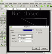
If it is a polygon go to Modify / Properties and select your object. In case the property menu offers the option closed then tick it. LibreCAD will insert a closing line element. If the object is a collection of connected lines you may transform it into a polygon (Draw / Polyline / Create polyline from existing segments) and repeat previous step.
There is no joint command for a selection of objects. Instead each element has to be touched and controlled.
Several options exist:
- Move
- Snap / Snap on endpoints
- Modify / Move
- Select segment
- Press enter
- Select endpoint of segment
- Select starting point of next segment
- Press OK
- Trim
- Modify / trim two
- Select first line to be connected.
- Select second line to be connected.
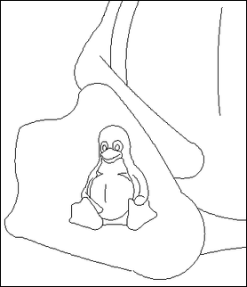
Another example: Please select View / Toolbars / Library browser. There you find Tux. Press import and copy him into the drawing window. You would have a hard time if you intend him to put on socks by adding hatchings. In the picture above the small penguin is surrounded by a magnified view of his right leg. The lines are composed out of arches, nearly none of them are interconnected.
Measure areas in maps
Data import and export
File formats
DXF is the exchange format for LibreCAD. You can export drawings as picture. You may choose PNG format. It compresses data losslessly. But it does not protect you against surprises. If you leave default picture size unchanged you will get quite small pictures in poor resolution. Like DXF the SVG format is a vector format and should present your data in any size.
Excerpt of a DXF file (linefeeds replaced by comma):
999, dxfrw 0.5.10, 0, SECTION, 2, HEADER, 9, $ACADVER,
1, AC1021, 9, $HANDSEED, 5, 20000, 9,  $DWGCODEPAGE, 3,
ANSI_1252, 9, $INSBASE, 10, 0, 20, 0, 30, 0, 9, $EXTMIN,
10, 0, 20, 0, 30, 0, 9, $EXTMAX, 10, 0, 20, 0, 30, 0, 9,
$LIMMIN, 10, 0, 20, 0, 9, $LIMMAX, 10, 420, 20, 297, 9,
$ORTHOMODE, 70, 0, 9, $LTSCALE, 40, 1, 9, $TEXTSTYLE, 7,
STANDARD, 9, $CLAYER, 8, 0, 9, $DIMASZ, 40, 2.5, 9,
$DIMLFAC, 40, 1, 9, $DIMSCALE, 40, 1, 9, $DIMEXO, 40,
0.625, 9, $DIMEXE, 40, 1.25, 9,  $DIMTXT, 40, 2.5, 9, .....
Excerpt of an SVG File:
<?xml version="1.0" encoding="UTF-8" standalone="no"?>
<svg
...
  width="744.09448"
  height="1052.3622"
  id="svg4153">
 <desc
    id="desc4155">line01.dxf - scale = 1.000000</desc>
 <metadata
    id="metadata4177">
   <rdf:RDF>
     <cc:Work
        rdf:about="">
       <dc:format>image/svg+xml</dc:format>
       <dc:type
...
Example: SVG import
LibreCAD cannot handle SVG data. But the open source program Inkscape can both import and export SVG and DXF files.
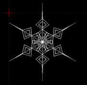
On the right there is an example of a snowflake. After SVG import to Inkscape and DXF export by Inkscape we can open it by LibreCAD. It looks really nice.
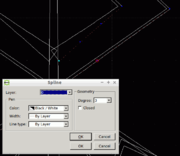
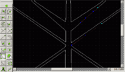
But a closer look reveals that areas are not rendered -- LibreCAD does not know areas, only (closed) lines. This has some unpleasant side effects. Lines are not transformed as lines but as (straight) splines of degree 3. Some lines crosses. This is quite strange if you are interested in a uniform boundary. Even worse some lines/splines are drawn twice. This is visible in the second diagram: The right line consists of a white untouched spline. On top of it is another spline. This one was selected and appears in a red dotted line.
Example: Bitmap import
Thanks to Inkscape we can even import bitmap pictures to LibreCAD:
- Import a bitmap graphic to Inkscape
- Convert to path, e.g. Inkscape 0.48:
- Path / Trace Bitmap / Brightness cutoff
- OK
- if required set fill to none, stroke to 1
- Save Inkscape image as filename.DXF
- Open filename.DXF by LibreCAD
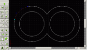
On the right side you see the input image. The second one is the result after import. As an example one element is selected. For the conversion algorithm it is not possible to find out that the image is composed of two circles. Instead it approximates the boundaries by splines of degree 3. Four to five splines form an inner circle. Unfortunately the elements are not connected, hatching will fail.
We can apply the same procedure to our snowflake. We get a better defined boundary lines in LibreCAD. But we lose information by the conversion from bitmap to vector graphic. Some lines are undulated and we lose full symmetry of the flake. (But if you have a close look at real snowflakes, you will find out that they also are not fully rotationally symmetric in a mathematical sense.)
Example: raw data import
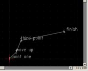
LibreCAD has an (experimental?) option for simple data import. If you have raw lists of data points which you cannot convert to DXF LibreCAD will do it for you. Try this data file:
1,0,0,0, point one
2,10,10,0,move up
3,17,27,0,third point
4,80, 40, 0, finish
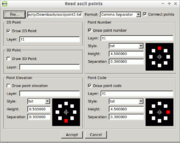
and save it as a text file. In LibreCAD create a new layer and call it t1. Go to File / Import / Read ASCII Points. On the right you see an example of the import window. Make sure that you choose the right separator, in our example Comma Separator. When you proceed you get 4 points connected by a line and titled according to your demand.
Grouping
You probably know grouping from other programs: select elements, press grouping -- and the elements behave like a single object.
LibreCAD requires some more mouse pressing. You group elements by Block commands. You can save each block into its own DXF file and manage them via library (View / Toolbars / Library browser. When you copy a block into your drawing you may access its element after selecting Modify / Explode. There are some entities which you cannot ungroup, for example hatching pattern.
There is an implode command as well: Draw / Polyline / Create polyline from existing elements.
Example:
- Draw / Line / Rectangle and paint a rectangle.
- Select the rectangle by left mouse clicking: you will select only a side not the whole rectangle.
- Repeat by Modify / Properties. Again you will be informed about one line only.
- Draw / Polyline / Create polyline from existing elements
- Repeat selection by left mouse. Now the rectangle is converted into a polyline which is even closed.
You can connect not only lines but arcs as well. Make sure that elements share one end- and start point, for example by snap / snap endpoints (see Closed Objects as well)
Splines
Self Test 2
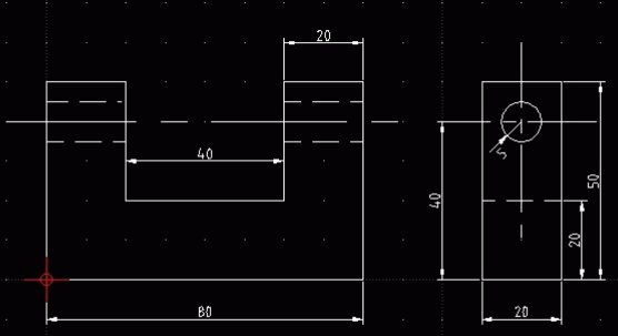
This time we have a clamping block. Again, if you get stuck along the way, refer back in the manual to refresh your memory. I intentionally left out a dimension so see if you can find where it should be. Hint: check the hole.
All the drawing we have done so far has been about sheet metal parts. The drawing tools you have learned so far can be applied to all drawings, whether they are sheet metal, landscape drawings, room layouts, or any other type of drawing. So what you learn here will hopefully be very useful.
Collection of DXF examples
(in preparation)
Technical background
Other resources
Lessons in using LibreCAD for knitting patterns
LibreCAD user Harry Guetter umbauwfb has authored some lessons about using LibreCAD for drawing knitting patterns.
These lessons may also be useful in learning how to use LibreCAD for other purposes.
The lessons are in PDF format and because they are too big for the Wiki, please find them in Harry's Box.com area.