We have moved to https://dokuwiki.librecad.org/
Lots of content was already moved to the new wiki, but there is still work to do. If you want to contribute, please register a new account at https://dokuwiki.librecad.org/
This wiki will be kept for a while to keep search engine results valid. Moved sites may be deleted here in future.
RU:Общее представление о CAD
Тут описаны основные понятия и идеи. Большая часть из них является общепринятыми в программных пакетах или в черчении.
Contents
Примитивы
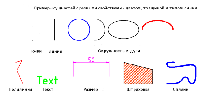
В программах для автоматического проектирования примитивами называют простые графические объекты. Типичными примитивами в большинстве CAD являются точки, линии, окружности и дуги. Более сложными и специфическими — полилинии, текст, размерные линии, штриховки и сплайны.
Каждый примитив обладает свойствами, например цветом, типом линии (длиной, непрерывностью и т. п.) и её толщиной. Ниже представлен пример.
Слои
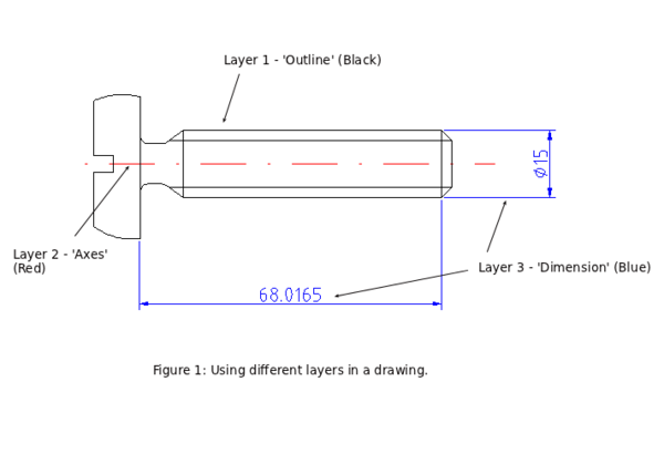
Основной концепцией в системах автоматизированного проектирования является использование слоёв для организации информации. В любом слое может находиться любое количество примитивов. Обычно примитивы с одинаковым назначением или общим атрибутом находятся в одном определённом слое. Например вы можете разместить все оси на чертеже в слое "оси" (см. рисунок 1). Слои могут иметь свои собственные атрибуты (цвет, толщина линии, стиль линии и т.д.). Каждый примитив может иметь свой собственный набор атрибутов или иметь атрибуты слоя в котором он расположен. В приведённом примере изменён цвет всех примитивов слоя "оси" на красный.
Слои использовались и в традиционном способе ручного черчения в инженерных, архитектурных и прочих чертежах. Они были нужны для для отражения дополнительной информации. Например для отображения осевых линий, или для разработки нескольких вариантов коммуникаций здания. Эти данные наносили на полупрозрачную бумагу и совмещали с основным чертежом для выбора окончательного варианта, который будет находиться на основном чертеже.
Блоки
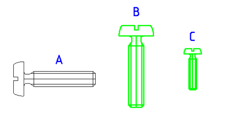
Блоком называют группу примитивов. Блоки можно размещать на чертеже произвольное количество раз с произвольными характеристиками — размер, цвет, местоположение, угол.
A Block is a group of entities. Blocks can be inserted into the same drawing more than once with different Attributes and at different locations and at a different scale and rotation angle (see image below) . Such an instance of a block is usually called an Insert. Inserts have attributes just like entities and layers. An Entity that is part of an Insert can have its own attributes or share the attributes of the Insert. Once created, Inserts are still linked to the Block they instantiate. The power of inserts is, that you can modify the Block once and all Inserts will be updated accordingly.
- Помните:
Блок становится частью файла с чертежом в котором был создан и был сохранён.
Создание и сохранение блоков — удобный способ многократного использования обозначений, например окон и дверей на чертеже плана помещения.
Блоками можно оформлять полезную текстовую, табличную и справочную информацию.
Пример вставки блока
|
A - оригинальный блок B - блок повёрнут на 270o (по умолчанию поворачиваем против часовой стрелки), изменены толщина и цвет линий C - Блок уменьшен |
Разработка в CAD
Во многих отношениях разработка в автоматизированной системе аналогична ручному черчению. Для создания плана или вида на бумаге нужны карандаш и линейка. В CAD существуют подобные инструменты. Огромным же преимуществом CAD является возможность, иногда в считанные секунды, изменить чертёж без больших усилий.
При работе с САПР можно легко создавать вспомогательные линии, опорные точки и т.п. для помощи в работе, но ненужные на конечном чертеже. Некоторые линии могут оказаться не той длины и их нужно будет укоротить, как на примере ниже.
Частой ошибкой начинающего разработчика является желание создать чертёж сразу в чистовом варианте. Без вспомогательных линий, контрольных точек и других подобных инструментов. Они являются важной и неотъемлемой частью любой САПР. Многие программы имеют массу средств для чистки чертежа от вспомогательных построений и подготовке его к печати.
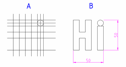
|
A - Создание вспомогательных построений B - Результат после очистки и обрезки концов линий |
Системы координат
Координатная система используется в большинстве CAD. Она задаёт место расположения точки отсчёта в пространстве рабочего листа которая имеет координаты 0,0. Значок глобальной системы координат находится в левом нижнем углу рабочего листа. В LibreCAD он выглядит как крестик красного цвета.
Вы можете задать единицы измерения для координатной системы.
Для текущего чертежа:
В главном меню: Правка -> Текущие настройки чертежа -> Единицы измерения (Edit -> Current Drawing -> Units).
Глобальные настройки (для всех новых чертежей):
В главном меню: Правка -> Настройки программы -> Умолчания -> Единицы измерения (Edit -> Application Preferences -> Defaults -> Units).
Выбор единиц даёт понять программе что значит "1 единица". Без такого определения команда "добавить 1 единицу к линии" может означать увеличение линии на 1 миллиметр или на 1 километр.
Более подробно: coordinate system
Object and Grid Snapping
When you want to specify and select a coordinate of an object/entity in LibreCAD, you can use the 'snap' tools which allow you to precisely 'snap to' grid points or significant points on existing objects: endpoints or midpoints of lines, center points, middle points and intersections etc...
More Details: Snap Tools
Basic Editing
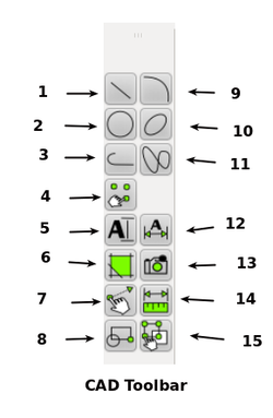
Entities can be inserted, selected, and, once selected, can be deleted, transformed or duplicated. To insert an entity means to draw it by selecting the appropriate drawing tool, such as line, arc, etc. from the main CAD toolbar (see image below), and by locating points that define the object to be drawn, such as the endpoints of a line.
1.Show line tools
2.Show circle tools.
3.Show polyline tools.
4.Draw points.
5.Insert text.
6.Create hatch.
7.Show modify tools.
8.Create block.
9.Show arc tools.
10.Show ellipse tools.
11.Draw splines.
12.Show dimension tools.
13.Insert image.
14.Show info tools.
15.Show selection tools.
Entity Selection
An entity must be selected before it can be deleted, duplicated, or transformed. Entity selection is one of the most basic of CAD operations. There are a wide variety of selection tools available to use in LibreCAD to quickly select groups of entities, entities within a range, connected entities, etc. (See image below).The selection tools are available from either the main menu - 'Select' or from the show toolbar 'Select' tools (no. 15 above).
Alternatively you can use the keycodes:
Ctrl-A - Select all
tn / Ctrl-K - Deselect all
Selection tools image to follow.
Deletion
Deleting an entity means to totally remove it from the drawing. In LibreCAD The deletion options 'delete' and 'delete selected' are available via the main menu > modify. The 'delete' option is also available from the 'modify' toolbar and by entering the keycode 'er' in the command line. See example images below.
Modifications
Basic modifications (changes) of an entity in a CAD system include translation, rotation, reflection, and scaling. These operations do not alter the characteristic geometry of the selected entity - however there are some CAD modifications that do - such as break, trim, extend or stretching of selected entities.
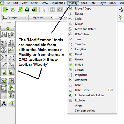
The modification tools are available from either the main menu > Modify or from the modify toolbar or by entering keycodes in the command line - see here: http://wiki.librecad.org/index.php/Commands_and_tools#Focus_on_commandline.
Dimensions
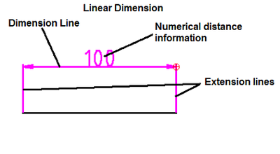
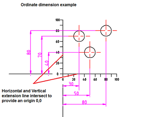
Required sizes of objects within a drawing are conveyed through the use of dimensions. Dimension 'distances' may be shown with either of two standardized forms of dimension - Linear and ordinate.
linear dimensions use two parallel lines - called “extension lines,” which are spaced at the 'required' distance between two given points.A line perpendicular to these extension lines is called a “dimension line,” with arrows at its endpoints. The numerical indication of the distance is placed at the midpoint of the dimension line, adjacent to it or in a gap provided for it!
Ordinate dimensions use one horizontal and one vertical extension line to establish an origin for the entire view. The origin is identified with 0,0 placed at the ends of these extension lines. Distances along the x and y axes to other points on a drawing are indicated using additional extension lines with numerical information placed appropriately.
Sizes of circular features are indicated using either diametral or radial dimensions. Radial dimensions use an “R” followed by the value for the radius; Diametral dimensions use a circle with forward-leaning diagonal line through it, called the diameter symbol, followed by the value for the diameter. A radially-aligned line with arrowhead pointing to the circular feature, called a leader, is used in conjunction with both diametral and radial dimensions. All types of dimensions are typically composed of two parts: the nominal value, which is the “ideal” size of the feature, and the tolerance, which specifies the amount that the value may vary above and below the nominal. Architectural Dimensions
Scale and Viewing
Unlike in manual drafting, there is no need when using a CAD program to first determine and work-out in advance the sheet size and drawing scale. When drafting with CAD, all sizes and distances are specified using their full-scale values,for instance drawing a 10 meter object in CAD is drawn as a 'real size' 10 meter object.It is only when it comes to printing that the drawing scale needs to be determined and adjusted based on sheet and drawing size.
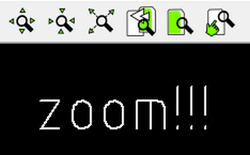
On the screen (in model space) the user can adjust the current visible area of the drawing by using the 'Zoom' tools, for example: zooming in to view more detail or zooming out to view a wider extent!
Zoom in
Zoom out
Auto Zoom , will zoom all entities/window to full extents
Previous view
Window Zoom , option to define a window to zoom!
2.Another important viewing operation in CAD is the use of 'panning' - panning allows us to to see another portion of the drawing without changing the display scale, a user pans to it by “moving” a rectangular display window until it's over the desired spot.
Zoom Panning, click and drag to pan zoom - a small hand icon will show when using this function.
In addition by pressing the middle 'scroll' wheel on most computer mouse devices will do the same thing here!
