We have moved to https://dokuwiki.librecad.org/
Lots of content was already moved to the new wiki, but there is still work to do. If you want to contribute, please register a new account at https://dokuwiki.librecad.org/
This wiki will be kept for a while to keep search engine results valid. Moved sites may be deleted here in future.
Spline tutorial 1
Contents
Introduction to LibreCAD and SPLINES to create a dolphin
Tutorial by Claudio Guarnieri
Greetings to all.
Firstly I realize that this tutorial may seem stupid, very stupid, but honestly I could not find anything to introduce the splines command, so I am sorry for my limited abilities to connect the very cad designing itself to real objects realized through designing like engines, ship profiles and so on.
This tutorial has been written in order to give a piece of advice in using the splines command and its options. I personally do not use splines, because I never had to, yet here I am in order to clear some doubt, at least I hope so; in this tutorial will be used the 2.0.3 version of LibreCad.
This is in a certain way, a simple topic, so, to whom that never used LibreCAD I suggest to get familiar with the basic commands, like “draw points, draw lines, draw polylines, move/copy”.
What are splines?
Wikipedia says “In mathematics, a spline is a sufficiently smooth polynomial function that is piecewise-defined, and possesses a high degree of smoothness at the places where the polynomial pieces connect (which are known as knots)”.
In this tutorial I will consider splines from a graphical point of view, so we can say that splines are lines that can pass through predefined points, we are going to draw a kind of dolphin, but splines are used to design plane or sips parts, or objects that have particular smooth shapes.
Splines settings
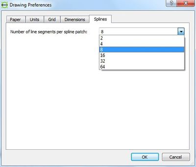
We are about to start then we need to define our splines settings. In order to do this we have to go to Edit – Current Drawing Preferences – Splines and define the number of line segment for the spline in the current drawing, the higher the number, the more accurate and smoother the line: notice that into the image below 8 segment are setted, this set is fair enough for our tutorial.
The command SPLINE itself
The spline icon ![]() is the icon that allows to create a spline. In LibreCAD there are two
types of spline: opened and closed: the option is selectable when the icon is pressed and
is displayed into the Tool option. To check if the Tool option is active click wit right
mouse button on a free area in the toolbar and look at Tool Option, if it is not selected
click with left mouse button and it will be displayed.
is the icon that allows to create a spline. In LibreCAD there are two
types of spline: opened and closed: the option is selectable when the icon is pressed and
is displayed into the Tool option. To check if the Tool option is active click wit right
mouse button on a free area in the toolbar and look at Tool Option, if it is not selected
click with left mouse button and it will be displayed.
In addition to the close option of splines there is the more important option, the degree of precision: there are degree 1, 2 and 3; the higher the degree, the more precise the spline will appear. Down here the spline tool option, notice that the close option is selected and the degree is 3. The spline command works through control points: we click the desired locations and we we will define the control points of the spline. Moving them once the spline is created, we will define the curve precisely. To move the points look at further sections in this tutorial.
Starting the draw (sistemare didascalia immagine)
Once we click the icon we will have to define the first point of the spline. Notice that control points are NOT snap endpoint; snap endpoint are the first and the last point on an open spline, endpoint are instead not present in a closed splines.
Then, after moving the control points we will obtain the desired shape.
The best way I experimented to get good splines is to draw simple points and use them
as reference to define the shape where the spline control points will be inserted. To
learn the principle of spline it would be useful to create a spline with a quite big number
of control points and model further the curve itself. Hatched are not implemented for
the very splines, but they can be inserted after exploding the splines.
To explode: Modify – Explode (click ![]() and
and ![]() ), some example down here.
), some example down here.

Hatching ansi31, paisley and hound
Hatches are not considered in this tutorial. Briefly, select the entities to fill, click on ![]() select hatch and scale, yet I wrote other tutorials where this function is examinated.
select hatch and scale, yet I wrote other tutorials where this function is examinated.
The dolphin itself
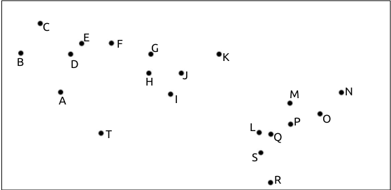
We are going to create a kind of dolphin using three splines, then the first thing to do is define the points of control of the body shape. If the coordinates are known it is possible to insert directly while defining the spline itself, The body coordinates are the following, indicated as POINT(Xaxis, Yaxis):
A(700,4000), B(300,4400), C(500,4700), D(800,4400),
E(900,4500), F(1200,4500), G(1600,4400), H(1600,4200),
I(2300,4400), J(1900,4200), K(1800,4000), L(2700,3600),
M(3000,3900), N(3500,4000), O(3300,3800), P(3000,3700),
Q(2800,3600), R(2800,3100), S(2700,3400), T(1100,3600).
Your situation should be similar to this down here:
Same method to the eye coordinates:
A1(900,4400), B1(1000,4400), C(900,4300), D(800,4300)
And finally the points that remain:
A2(1000,4000), B2(1200,3800), C2(1400,3700), D2(1600,3700), E2(1500,3900)
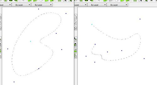
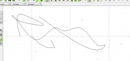
Now we can create the three splines. We will consider SPLINE 1 that will be the body, SPLINE2 the eye, SPLINE3 the fin, I let you decide your splines' degrees. SPLINE1 and SPLINE2 are closed splines, while SPLINE3 is not closed. It is important to follow the coordinates order, otherwise the result may be a different, down here in the picture I intentionally clicked randomly.
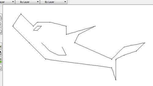
If you followed correctly the coordinates order your result should be like this down, I
have chosen “Degree 1” on splines command Tool Option.
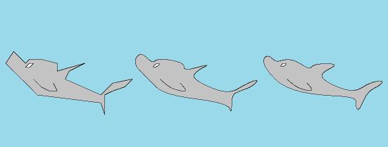
Now we can delete the points or move them to create splines having different degrees.
To select entities we can click each entity, or we can use a better way.
Click left mouse button, keep it clicked and try to move the mouse, it will appear
aselection area: if this selection area appears blue, all the entities totally inside the area
will be selected, if the colour of the area is green, all the entities touched by the area will
be selected, even if they are not contained totally into the green window.
Finally to move/copy there is to do: ![]() +
+ ![]() give confirm and select the coordinates
of the reference and target point; remember that if you are not using the snaps you
need to insert x and y coordinates (X “comma” Y) to give absolute coordinates, or
@before X and Y to give relative coordinates, for example 500,0.
Down here others examples obtained with degrees 1, 2 and 3:
give confirm and select the coordinates
of the reference and target point; remember that if you are not using the snaps you
need to insert x and y coordinates (X “comma” Y) to give absolute coordinates, or
@before X and Y to give relative coordinates, for example 500,0.
Down here others examples obtained with degrees 1, 2 and 3:

Spline degree 1, degree 2 and degree 3
Final remark and conclusion
In this tutorial I did not mention it, but when you are drawing a spline, remember to use the undo button on Tool Option to undo the last control point in case of errors. With this piece of advice this tutorial ends here.
I wrote this tutorial to give some kind of help, even if I repeat that I never used the splines tool, or curved lines. I tried to do my best to be helpful and I hope this tutorial helped someone, at least a little. If you find something wrong do not hesitate to say.
See you soon!
Claudio
