We have moved to https://dokuwiki.librecad.org/
Lots of content was already moved to the new wiki, but there is still work to do. If you want to contribute, please register a new account at https://dokuwiki.librecad.org/
This wiki will be kept for a while to keep search engine results valid. Moved sites may be deleted here in future.
Coordinate system
The Coordinate system
In order to get the best out of LibreCAD it is wise to have a good understanding of the coordinate system and how coordinates work. Everything that you draw in LibreCAD will be exact and precise and will be placed there accurately based on the X,Y coordinate system.
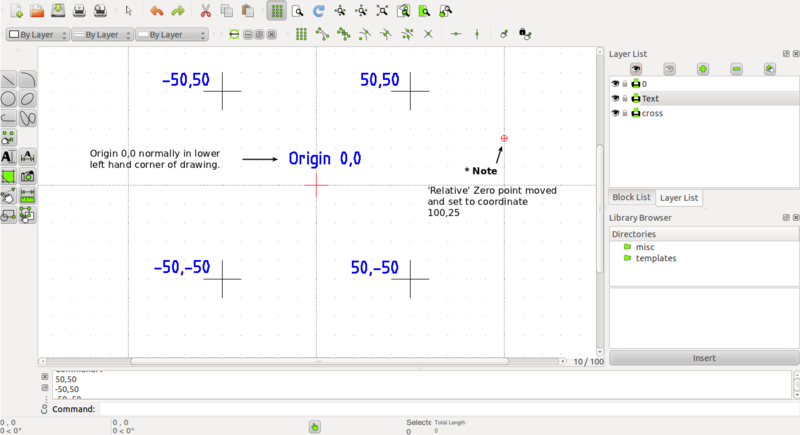
The absolute origin or Zero point in your drawing is where the X and Y axes cross each other (represented by a Red cross), every entity you draw is located in relation to this origin.
In LibreCAD there is also the option to set the Relative Zero Point (small red circle).This Relative zero point can be temporarily set to a new location in a drawing so that all subsequent X and Y coordinates of entities drawn or blocks placed for example will be relative to this newly set Relative Zero Point.
In libreCAD`s 2D coordinate system all X units are measured horizontally and all Y units are measured vertically. Coordinates can also be shown as 'Positive' (+) or 'Negative'(-) values.
Examples of X and Y coordinates
Basically there are two types of Coordinates Cartesian and Polar.
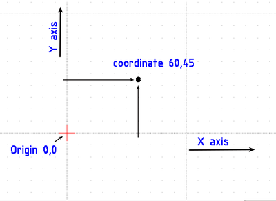
The Cartesian coordinate system is generally the standard system used in most CAD programs. A specific point in a drawing is located by exact distances from both the X and Y axes - for example a point in a drawing could be 60,45 (note the comma -, separates the two numbers).See example Image below.
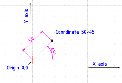
The Polar coordinate system uses one distance and one angle to define a point in a drawing -for example a point in a drawing could be 50 < 45, so 50 units long and at an angle of 45 degrees (note the < sign is used for the angle). see example image below.
In LibrecAD lines,points, Arcs, Polylines, Circles and many more entities can be drawn and placed in a drawing using either Absolute or Relative coordinate input.
To input coordinate value points in LibreCAD you can 'type' your values in the command line or inside a 'text input box' (presented by tool options requiring distance,angle etc...).This method is 100% accurate.
Or
You can 'manually', move the mouse cursor around and visually pick a coordinate point, but obviously this method is less accurate but may be acceptable for some 'rough' sketch or freehand work!
Absolute coordinates - using this method,coordinate points are entered in direct relation to the Origin 0,0. To do this in LibreCAD just enter in the exact point e.g. 60,45.
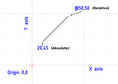
Relative coordinates - using this method, coordinate points are entered in relation to the previous point entered (not the origin), so for example - if your first point is 20,45, to then enter your next point 'relative' to this - you would use the '@' symbol - e.g @50,50 would then enter the second point 50 units horizontally along the x axis and 50 units vertically along the Y axis to give this second point relative to your last point (20,45).See image below.
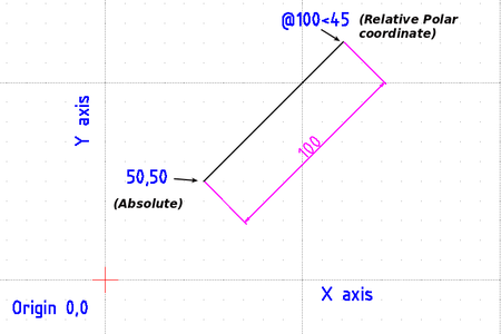
Relative Polar coordinates - this is a very useful way of drawing entities of which you know the exact length and angle.
For example you could draw a 100mm long line from start point 50,50 (absolute coordinate) and specify your second point at 100<45 (relative 'polar' coordinate).
You can see from this example that the second point is based on our 'distance' of 100mm and at an angle of 45 degrees. See example image below.
Angles in LibreCAD
It is worth mentioning here a brief explanation of how angles work in LibreCAD.
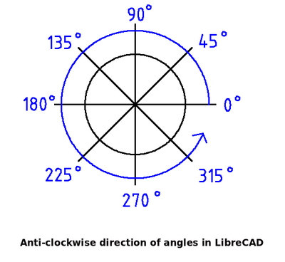
All angles in LibreCAD are measured in 360 degrees in an anti-clockwise direction (see image below) beginning from 0 degrees (the 3 o'clock position). The < symbol is used before the angle - e.g.50<45.
