We have moved to https://dokuwiki.librecad.org/
Lots of content was already moved to the new wiki, but there is still work to do. If you want to contribute, please register a new account at https://dokuwiki.librecad.org/
This wiki will be kept for a while to keep search engine results valid. Moved sites may be deleted here in future.
Difference between revisions of "Starting to draw"
(→Construction lines) |
(→Construction lines) |
||
| Line 31: | Line 31: | ||
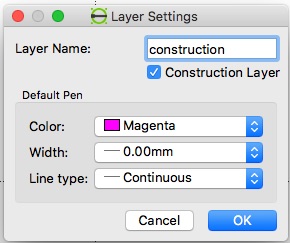
# Create a new [[Layers#Construction_Layers|Construction layer]] with a name such as 'construction', and a colour of magenta or cyan or similar. The line's width should be '0'. [[File:Construtionlayerdialogexample.jpg]] | # Create a new [[Layers#Construction_Layers|Construction layer]] with a name such as 'construction', and a colour of magenta or cyan or similar. The line's width should be '0'. [[File:Construtionlayerdialogexample.jpg]] | ||
# Make sure ''[[Snapping|Snap]] on grid'' is enabled. | # Make sure ''[[Snapping|Snap]] on grid'' is enabled. | ||
| − | + | ||
| − | # | + | === Drawing Box === |
| − | # | + | We'd like to create a 5000 x 1300 mm construction line drawing box in which our construction will be placed. |
| − | # | + | # Hit space to enter the command line mode - the cursor will jump to the lower right corner and "Command" will be in blue |
| + | # Type polyline or "pl" - you'll now asked for the points | ||
| + | # Specify first point: 0.0 | ||
| + | # Specify next point: 5000,0 | ||
| + | # Specify next point or <nowiki>[undo]</nowiki>: 5000,1300 | ||
| + | # Specify next point or <nowiki>[close/undo]</nowiki>: 0,1300 | ||
| + | # Specify next point or <nowiki>[close/undo]</nowiki>: close | ||
== Outlines == | == Outlines == | ||
Revision as of 08:02, 6 November 2018
This page presents a simple sequence of creating a basic drawing, from a blank document to a printed design. It assumes that you have installed LibreCAD and have opened it to a new default blank drawing. It introduces quite a few LibreCAD concepts, and links to other pages that explain these.
Contents
Sketching
The first part of any design is a freehand sketch on paper. This is quick and simple and so allows for greatest freedom in the design process.
Example
We'd like to create a drawing of the following alumnium structure:


Start a drawing
- Start LibreCAD
- First you might want to decide about your application preferences using Options/Application Preferences/Appearance
- For this example the background color has been changed to "white"
- Save the default "unnamed document 1" as "CarportEast" using the "File/Save" Menu
- Check that the save was successful by Quitting LibreCAD, and restarting it. The saved file "CarportEast.dxf" should show up in the "File/Recent Files" Menu
- Reopen the file and close the "unnamed document 1" by clicking the circled x in the tab.
Scaling
We'd like to have an A4 drawing on which a scaled version of the 5000 x 1300 mm construction fits.
A4 is 297 x 210 mm so if we make the 5000 mm be shown as a 250 mm long line we'd be set. That is a 1:20 scale.
Via the menu Options/Current Drawing Preferences/Dimensions we can se the General Scale to 20 to achieve the scaling.
Construction lines
The first lines of any technical drawing are the construction lines, setting out the locations of all lines without specifying any line types, colours, etc. All straight construction lines are of 'infinite' length — i.e. they extend off the screen in both directions.
- Create a new Construction layer with a name such as 'construction', and a colour of magenta or cyan or similar. The line's width should be '0'.
- Make sure Snap on grid is enabled.

Drawing Box
We'd like to create a 5000 x 1300 mm construction line drawing box in which our construction will be placed.
- Hit space to enter the command line mode - the cursor will jump to the lower right corner and "Command" will be in blue
- Type polyline or "pl" - you'll now asked for the points
- Specify first point: 0.0
- Specify next point: 5000,0
- Specify next point or [undo]: 5000,1300
- Specify next point or [close/undo]: 0,1300
- Specify next point or [close/undo]: close
Outlines
Once all the construction lines are drawn, add a new layer. This time not a help layer, and instead of 0-width lines, use 0.25 mm black ones.
Ensure that 'snap on intersection' ![]() is turned on.
is turned on.